Maker Pro
Maker Pro

Battery powered Current sink with low voltage cutoff

I did look at pin 1 and there was only a small ripple
I will soon post a schematic with more values as you requested.
The board was laid out in Corel and I don’t know if you could read it, but will try to put it in a jpeg.
The 68k resistor you see is really two resistors making it 150k, because I'm using 47k pots.
I do check every value before I put them in.
 
Layout

Hope you can read this, voltages to follow, as requested.
So far after rebuilding it for the fourth time, I was unable to get it to turn off. Once the turn on/off problem is solved the rest is easy.
Regards,
G.
EDIT please don't use this one, see next.
 

Attachments

  • Constant Current Load layout.jpg
    Constant Current Load layout.jpg
    97 KB · Views: 140
Last edited:
sorry

Please use this instead of the previous… sorry
 

Attachments

  • Constant Current Load layout.jpg
    Constant Current Load layout.jpg
    97.6 KB · Views: 132

KrisBlueNZ

Sadly passed away in 2015
OK. I'm looking at the layout now. Can you modify your schematic so it shows the actual component values you've used please.
 

KrisBlueNZ

Sadly passed away in 2015
OK, here are the errors I've found so far. I'm working just from your layout drawing, comparing it to my schematic. Your schematic has different component references and at least one componet (QP) has the wrong part number.

Many of these errors are probably fixed in your actual stripboard prototype but not in the layout drawing. Obviously, it's important to keep everything in step, when you're working with two schematics, a layout drawing and a prototype, otherwise things get crazy!

The 8-pin IC is a TLE2022 not a TL431
Missing track cut between power input negative and QP gate
Missing track cut between DR anode and DL cathode
Missing track cut between QH drain and +8V rail
Missing wire between RN, RM junction and QH gate
Missing track cut between QH gate and TL431 centre pin
Missing track cut between RN, RM junction and VRM
VRT potentiometer left hand end and middle terminals swapped (middle terminal is wiper)
QS mislabelled as Q5

Those aren't necessarily all the errors on the layout diagram. I think it's best for you to check it over and fix everything you can find. Once you've done that, post it and I'll have another look.

BTW diagrams are usually better exported as GIF files (or compressed PNG) than JPEG. The JPEG file format is designed for pictures (that's what the P stands for, after all) and doesn't handle line drawings and computer-generated diagrams well. Use either 2-colour or 16-colour GIF. You may be able to export at a higher resolution and still fit the file into the 100kB forum limit.

Edit: Compressed PNG is also good for drawings/diagrams.
 
Last edited:
Thank you thank you!

Thanks, Ill work on it today, and report.
I used the stripboard diagram as a tool in the layout location. I didn't lay out the parts by it rather I used the schematic diagram. I also re bread-boreded it and got the same results. I don't see the possibility of making a mistake 4 times in a row, but the device always acts the same, that being when power is connected it turns on(switch in auto) and SW1 has no effect on the circuit.
Is it possible for you to send a simplified schematic of just the on off portion without any other components? On paper it looks like it works, but in practice it refuses to respond, how rude!
The other possibility would be to take the attached diagram, that is working and tested many times, and modify it into your circuit? I made several small small units, that just plug in to the board for a single button on off.
I will not give up on your circuit and will rebuild it from scratch if I have to, but that would be the 5th time. I so much appreciate all the time you are taking, to help me in this project, and I hate to look a gift horse in the mouth, but is it possible the on/off portion of you circuit has a glitch?
Best regards,
G.
 

Attachments

  • On-OFF.png
    On-OFF.png
    7.2 KB · Views: 124

KrisBlueNZ

Sadly passed away in 2015
It is quite possible to make a mistake four times in a row, if it's the same mistake.

I understand that you would rather have a single pushbutton for ON/OFF control. I will think about modifying my circuit to have that feature, but not for the next five days - I'll be at my partner's place, and I like to spend as much time as possible with her.

Yes, it's definitely possible that the ON/OFF part of my circuit has an error; maybe more than one. But at the moment I'm concerned that pin 1 of the TLE2022 is not properly low nor high. I think that's most likely to be due to a wiring error. I would like to see the voltages and waveforms on pins 1, 2, 3, 4 and 8 of the TLE2022.
 
Hi Kris,
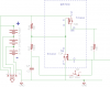
Well, I have good news, and better news. First the good news; After looking at the waveforms I ascertained that my circuit was getting feedback from the high currents, affecting TLE2033(1,2,3) so I tried various ways to isolate the TLE2022. The final solution was to add a TLP222A1 photodiode as a means to isolate. It worked, and very well. Now as seen on the scope, the rise time is very fast (< 1mS) and no chatter at all. I testes it up to 2 AMPS, and had no problems. I set the 20K trim pot for a max of 1.5 AMP. I also added a second meter and a push button for battery voltage/set cutoff voltage. As you can see I used much of you circuit in the design. Thank you again!

Now the better news I spent a lot of time wondering why your circuit wouldn’t work and started trouble shooting it. I found that QH and QK were shorted Source to drain. What are the chances? I replaced them, and still it would turn on when power was supplied, and would not turn off.

After much head scratching I found that resistor RG (33k) was the problem. I replaced it with a 4.7k and low and behold it would turn off with SW1. There was still a problem, that being U1A pin 1 would swing logic 1 to logic 0, but the circuit still would not turn off. I found that resistor RM (10k) was the problem. It was not turning on to the point of turning QP off. I replaced it with a 2K resistor and it all came together. It now works as advertised!
So there you have it, two circuits, both working. I like your circuit better than mine, because it is so elegant. Let me know if there is another way to mod your circuit other then the fix I employed.

Please comment, and again, thank you so much for taking the time to help me out, your knowledge of electronics is amazing!
Best regards,
Greg
PS attached is my circuit and Kris's layout
 

Attachments

  • BPCS-9.png
    BPCS-9.png
    35.8 KB · Views: 132
  • Kris layout 3.gif
    Kris layout 3.gif
    45.1 KB · Views: 121
Last edited:

KrisBlueNZ

Sadly passed away in 2015
Hi Greg,

I'm glad you have a circuit that you're happy with.

I think the optocoupler you added in the power-up/power-down control loop may have fixed the problem not because it provides isolation, but because of its delayed turn-off. If it delays the feedback loop long enough for the supply rail to fall to a low enough value, that will prevent the oscillation that was causing your circuit to power back up while it was trying to shut down. I'm not sure about this explanation though.

I'm not confident in your explanations of the changes you made to my design, especially changing RM from 10k to 2k, but if you're happy with the result, then I'll let sleeping dogs lie :)

I'm glad you're happy with the design.
 
Hi Kris,
I think you may be right about the optocoupler, as I was playing around with a RC time delay before I put in the opto.
On your circuit, I hooked a resistance box in place of RM and it would not turn off with more than a 2.3k in it’s place. The voltage at QP gate was just enough to keep it on. Is there something else I could try?
Regards,
G.
 

KrisBlueNZ

Sadly passed away in 2015
I just noticed that the optocoupler's collector and emitter are reversed on the schematic. The emitter should be connected to the 0V rail. I assume your prototype has the correct connections; if it doesn't, I can't see how the optocoupler would work at all.

I'm not happy with the RM change because the way you've described it, it pretty much makes it impossible for comparator U1A to turn QH ON. Even with U1 pin 1 at 11.0V, if RH and RN are both 10k and RM is 2k, you will only have about 1V on QH's gate, which is not enough to turn it ON. So I think that by reducing RM to 2k you have actually defeated that part of the circuit. If that caused the circuit to start working, then there is obviously something wrong somewhere. My guess is that it's a layout error in the prototype board.

Mucking around with a design using a resistance box is not a recommended engineering approach to fixing a problem, especially if you can't explain how the apparent "fix" works, and doubly especially if the apparent fix should in theory break the circuit!

Back around post #53 on this thread, we were taking an engineering approach - looking at the voltages and waveforms in the circuit and trying to figure out where the problem was. I identified the 3.2V voltage on pin 1 of the TLE2022 as being wrong. Later in post #67 I identified several errors on the prototype layout drawing. You didn't reply directly to either of those posts and I can't tell whether you have followed up any of my suggestions. If you want to "try" something else, I'm not going to suggest that you change some more component values at random; I think you should be methodical and continue from those points :)
 
Well, you’re right again. I looked at the data sheet again and the emitter should go to 0V rail, but it works either way, I tried both with no apparent difference. Go figure.
I’m sorry I didn’t get back to you about the post 67, I did invoke all your suggestions. I had a friend solder up a new board, and we both checked it twice, and could find no errors, my bad.
I’ll put back the original 10k and 33k resistors and post a schematic with all the voltages. I’m sorry, I’m trying to get my mind to work in a more methodical way, but the other me says “fix the problem” thus the playing around. I’m getting better.
Just when you thought it was OK to go back in the water….
Regards,
Greg
PS If you check post 47 you will see an actual diagram drawn from the circuit.
 

Attachments

  • BPCS--9A.png
    BPCS--9A.png
    29.8 KB · Views: 147
Last edited:
I’m supplying the 2 following diagrams, one is voltages on the board, and two the layout, reproduced from the board. The voltages were take with the SNK set to 4.00V and the cutoff set to 5.00v The SW1 was in AUTO and the circuit turned on when power was supplied, and could not be turned off.

I had a friend build this circuit up so as to eliminate any errors I may have made, and it acts the same as the one I built up. I circled some voltages that were specious.

The reason I used my resistor box was after looking at the voltages and the waveforms, and looking up the spec. sheet on QP, found there was too much voltage on the gate to turn off. That’s when I changed RM and RG, causing it to work, but as you say something isn’t right.

I had to redraw your circuit, because I don’t have your software for drawing (what is it?) and I hope I didn’t make any errors, but anyway it’s the voltages you’re after. Need any other readings or waveforms?

Buy the way, I found the meters loaded down the circuit, the impendence of which is about 70K, so I think I will have to use a voltage follower on them.
Regards,
Greg
 

Attachments

  • Constant Current Load.GIF
    Constant Current Load.GIF
    42.5 KB · Views: 104
  • BPCS9B Voltage.png
    BPCS9B Voltage.png
    34.3 KB · Views: 112

KrisBlueNZ

Sadly passed away in 2015
I had a friend build this circuit up so as to eliminate any errors I may have made, and it acts the same as the one I built up.
Did he work from my original schematic?
Buy the way, I found the meters loaded down the circuit, the impendence of which is about 70K, so I think I will have to use a voltage follower on them.
OK. You could use a TLE2024, the quad version of the TLE2022. The main reason I chose the TLE202x over the LM324 or other low-quality devices is the low offset voltage.

I think your schematic is right. (My diagram is drawn with a very old program called OrCAD/SDT III which runs on MS-DOS. I can't send you a copy. But it's fine for you to use LTSpice, or whatever you're currently using.)

The voltage you are measuring at the junction of R4, R9 and C1 is wrong. Somehow you are getting 2.22V at that point. It must be coming from somewhere. I guess there's a short somewhere.

There is also something strange about the QH gate voltage. You have marked it twice; one marking says 1.23V and the other says 1.08V. Those voltages should not be enough to turn QH ON, but its drain is sitting at only 2.4V. That is why the circuit is not turning off.

Try shorting from QH gate to QH source (the 0V rail). If the circuit doesn't turn off, there is something wrong with the connection between QH drain and QP gate - probably another short circuit. In fact it could be that connection that's shorted to the junction of R4, R9 and C1.

The layout has at least one error: I can't see the connection from pin 1 of the TLE2022 to the gate of QH. There are supposed to be three 10k resistors and a capacitor in the path but I don't see any of them. That is not necessarily the only error but it's a good place to start.

Also there should be four track cuts underneath the TLE2022.
 
Top