Maker Pro
Maker Pro

Advice about MC34063 based buck converter diagram

Well i am alredy using the pin's method to connect my boards. I have the arduino board, one Interface board and one I/O board all connected "back to back" so i would like to have the PSU biult in the I/O board and not as separate board.
Purely due to my projects design.
 
I received the 34063 today and started experimenting on the breadboard.
I used the values recommended by the design tool. I gave it the following parameters:
Vin=12V
Vout=5V
Iout=500ma
Vripple=60mv
So it gave me the following values:
Ct=947 pF
Ipk=1000 mA
Rsc=0.3 Ohm
Lmin=142 uH
Co=104 uF
R1=1k R2=3k (5V)
Now i used a coil of 200uH, Ct 1000pf instead of 947pf and Co=220uf (also tried 1000uf)
without any load connected it shows very large ripple on the output (about 200mv pk-pk).

What am i doing wrong here ?
 
Put a load on the output. It could be the error amplifier having a bit of a struggle with the fact you have no load on you supply. They tend to spend a lot of time turning on and off in that situation instead of exercising a more linear control. It might also be that any compensation is not correct. SMP's tend to be a bit noisy anyway, it's just a matter of scale.
A final thought. Is the ripple H.F or a somewhat lower frequency? is it spiky or rippley?
Can you get a pic of it?
 
Yes i can get pictures. It looks ripply to me. At the moment i am going through my connections again to make sure that i have everything okay on the breadboard. I do suspect the breadboard itself causing this though.
 
Adding a 100nf ceramic capacitor between pin 1 and pin 2 seems to help alot but still after adding load (the actual arduino board with an LCD) things get really ugly.
all pictures are with the load attached.
picture 0 shows the output with a 220uf output capacitor.
picture 1 shows the output with a 1000uf output capacitor.
picture 2 shows the output with the 100uf cap and a 100uh inductor (terrible)!
 

Attachments

  • TEK00000.PNG
    TEK00000.PNG
    10 KB · Views: 10
  • TEK00001.PNG
    TEK00001.PNG
    9.8 KB · Views: 10
  • TEK0002.PNG
    TEK0002.PNG
    10.3 KB · Views: 9
Okay. i used the diagram as in the datasheet with slight modifications as shown below and i got it working. now i will try adding the optional output filter to see what happens.
 

Attachments

  • buck conv diagram.png
    buck conv diagram.png
    25.9 KB · Views: 8
Try a larger cap on the output. I have just designed a switcher in simulation,for use with gloplugs for my model aero engines to use with a 12V battery. It supplies up to 15A or so at between 0.9 to 1.5V. It runs at about 120KHz and has 2 2200uF caps on the output. I have bee investigating a filter on the O/P as well but am not certain that it is worth the extra components. It too produces ripple similar to your at a light load as the error amp turns the PWM on and off because of the light load. So, as I said in a previous reply, you need to load the O/P so that the error amp is not forcing the PWM to be switched on and off in order to control the O/P.
The inductor looks a bit large in value which can affect ripple. What is the switching frequency of your circuit?
 
i think it is 40Khz. since Vin=12V Vout=5V and Ct=470pF.
The problem is that i do not have good quality low ESR capacitors...
 
I wonder how the capacitor i placed between pin 1 and pin 2 affects the circuit and reduces ripple. I saw it in a car USB charger that i have...
 
I should probably make a new thread about this question but anyway. I see that the buck converter is noisy no matter what so im thinking that since my project is of big importance and i need tie microcontroller to be as reliable as possible. i could try feeding the 12V to an 7809 Vreg which in turn will feed the 7805. this way heat dissipated from each chip will be significantly less that the heat dissipated
 
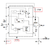
You could try a parallel resonant filter in series with the output. It does work. You have to tune the filter to the fundamental of the ripple. It works by presenting a very high impedance to the ripple. The only downside is that it only works at one narrow band of frequencies and if there are significant harmonics above that, they won't be affected.
The formula to calculate is (1/6.284) * (SQRT (C*L)), where C is expressed in Farads and L is expressed in Henries.
3.3μH in parallel with 4.7ΩF will resonate at 40.4KHz which is close to your quoted value. Note, the Inductor should have a very low DC resistance, preferably in the low milliohm region as this will affect the Q of the circuit.
 
It looks like that i am not able to measure the ripple with the Oscope. I have builded the circuit on a PCB and things are alot different now. I will show pictures.
 
You could be sweating over nothing here
Maybe but i am not sure. I will explain.
I use the arduino mega 2560 (pro mini boad) like this one:
https://www.makerlab-electronics.com/product/arduino-mega-2560-pro-mini-atmega2560-16au-ch340g/
Also i have in use many inputs - outputs plus i have other attiny chips powered from the same source.
The atmega board in its back it states that the working voltage is 7V-9V (peack 18V).
So i do not think that the onboard regulator can handle this current.
 
Top