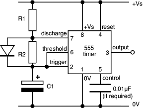
The problem is that there are three errors in the schematic, and one of them is critical.
As with all standard 555 astable circuits, the two timing resistors interact; without adding diodes, you cannot have one be on time only and the other be off time only. Without diodes, the on time always will be equal to or greater than the off time, never less. There is a circuit in the CMOS 555 datasheet that can be modified with two diodes for much better performance.
Note: the two pots are labeled incorrectly. That's two small errors.
The big error is that the 1N4001 is backwards. As shown, it bypasses the lower pot curing the discharge part of a cycle, so the lower pot has almost no effect on the output frequency.
If you reverse the 1N4001 diode, you will be close. With the diode reversed, the cap will charge up through the upper pot while the lower pot is mostly bypassed by the diode. This is the ON time adjustment. As is normal for a 555 astable, the lower pot will adjust the OFF time without interference from the upper pot.
Increase the two 100 ohm resistors to 1 K each. This will protect the 555 Discharge output from excessive current if the pots are set to 0 ohms accidentally.
ak


