Below is the LTspice simulation of a 555 astable circuit with the output On (green trace) when the Enable input (yellow trace) is 5V and Off when the Enable input is 0.6V.
Note that the first 555 pulse is longer than the rest (typical when the 555 starts oscillating), and the last pulse can be truncated depending upon when the Enable signal goes low.
Does that do what you want?
View attachment 53481
If the increase in the first pulse-width and the truncated last pulse is a problem, then a JK flip-flop can be used to gate the signal and eliminate these variations (simulation below using a CD4027 JK-FF).
The 555 is now running continuously (at double the frequency due to the divide by two output from the flip-flop).
Since the gate signal and the 555 output are not
Below is the LTspice simulation of a 555 astable circuit with the output On (green trace) when the Enable input (yellow trace) is 5V and Off when the Enable input is 0.6V.
Note that the first 555 pulse is longer than the rest (typical when the 555 starts oscillating), and the last pulse can be truncated depending upon when the Enable signal goes low.
Does that do what you want?
View attachment 53481
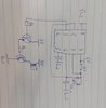
I tried it and it doesn't work. My senzor output stays low. I tried different Rezistor configurations and still. I'm using 55100-3H-02-A hall effect. I had to use not gate, because it has sinking putput. This is my schematic for it. I had to use pull up Rezistor for senzor. Do u know, where problem may be? Tranzistors used are the same npn BC549C. Thank u for ur time