Maker Pro
Maker Pro

Problem with Ramp signal Generator using IC 555

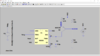
According to theory the time period for ramp signal generated using the following circuit should be:
T= [2.Vcc.C1.RE . (R1+R2)] / [(3Vcc .R2 ) - (3VBE.(R1+R2))]
Now... putting the value of Vcc, R1, R2, VBE, RE... the time period comes out to be around 0.9ms.
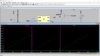
But from the simulation it appears to be around 3ms.
Whats wrong here?
 

Attachments

  • Screenshot (735).png
    Screenshot (735).png
    154.3 KB · Views: 14
  • Screenshot (736).png
    Screenshot (736).png
    163.4 KB · Views: 10
Did you measure the accuracy of your R & C used in timing loop ?

Datasheet says -

upload_2022-5-9_13-19-7.png

What accuracy are you seeking ?

Fixed frequency or variable needed ?


Regards, Dana.
 
The Thevenin equivalent resistance of R1 and R2 is 31 K. That is a pretty high base resistance, so the voltage at the Q1 base will not be very "stiff". That is, it will change as the collector voltage ramps up. As the collector-emitter voltage changes, the transistor gain changes, so its base current changes. The base current goes through R2, which changes the voltage at the R1-R2 node. Because R2 is so large, a very small change in base current is noticeable. This affects the linearity of the ramp waveform.

ak
 
Last edited:
Alec: The problem is not Vbe; it is hfe.

If you run the numbers assuming a transistor gain of 50, it almost perfectly explains why the sim voltage at the R1-R2 node differs from the Thevenin equivalent by around 1 V. That is 10 uA through 100 K.

TS: Where did that equation come from?

Also, as a test, divide R1 and R2 by 1000, leave everything else the same, and see how this affects the base voltage and the sim.

ak
 
Last edited:
Top