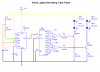
Here's a design for you to look at.
I've split it up into modules. Starting at the top right corner is the DC input conditioning circuit. You will need one of these to clean up the 12V supply from the vehicle, which can have interference and large surges on it, which can cause misoperation and/or damage.
The VDD and VSS arrows on the left of this module supply power to the logic ICs (in the modules at the left). Each IC must have a decoupling capacitor, 0.1 uF ceramic, connected between its VDD and VSS pins as close as possible to the IC. These are not shown on the schematic but you DO need them, to prevent glitches and incorrect operation. They are especially important in electically noisy environments, which yours is.
Below that is a single LED driver. It can drive at least ten LED pods in parallel (you said that each one draws 38 mA). Obviously, all the LED pods that you connect to a single driver will all have the same display, i.e. they will all be ON at the same time, and OFF at the same time. In your application, you will need TWO of these LED pod drivers.
The main switching device is an N-channel MOSFET. I have listed three alternatives, all of which are very cheap. The first suggestion is definitely the best. MOSFETs need to be handled carefully because they are sensitive to static electricity. Google for guidelines on handling MOSFETs.
The three modules on the left generate control signals for the LED pod drivers. The first one generates the "strobe" pattern, but I designed it before I saw KJ6EAD's suggestion, which is probably better. The second one generates the same pattern as KJ6EAD's circuit. The third one generates the "wig-wag" pattern.
Each of these signal generator modules has two outputs, one for "left" and one for "right", which you need to connect to your LED driver modules. I haven't shown any switch selection to let you choose between patterns, because I don't have a clear understanding of what you want to do. I thought I would give you these ideas and let you play around with them, then when you can explain exactly what you want, I can add circuitry to do it.
The circuitry is based around CMOS CD4000-series ICs. These are an old technology but are still readily available from Digikey or Mouser, and possibly your local electronic parts shop. In the schematic, some ICs (CD4013 and CD4017) are shown as a single block that represents the IC and has the pins in the same order, but other ICs (the CD40106 and the CD4053) are shown as smaller symbols. These ICs contain several identical functions inside them, and in this diagram, I have shown these individual functions as separate elements. It is up to you to allocate these functions within the ICs you have.
This might seem like an extra complication for you, but it makes it simpler if you want to add extra patterns later. If you're adding a circuit that needs one element from a CD40106, and you know that a CD40106 has six of those little symbols in it, and you have a spare element in a CD40106 in your design, you can allocate that to the new circuit.
I expect you will want to prototype this on breadboard, with an adapter or small battery as a power supply. In that case, you don't need to make up the DC voltage conditioning circuitry - that's only needed when you're running it in the vehicle.
If anything is unclear to you, feel free to ask.
")