Maker Pro
Maker Pro

PIR LED 12V light circuit recommendations wanted.

Harald Kapp

Moderator
Moderator
The transistor's terminals aren't labelled in the drawing in post #14, which represents the transistor as a rectangle with 3 leads.
I was referring to post #16 with a correct symbol.
This is the problem with the kind of "schematics" as shown in #14: using non-standard symbols makes understanding hard. Presumably the box shows the frontal view of the transistor, Acc. to the datasheet the pins are from left to right
C-B-E
upload_2022-1-29_12-22-12.png
which fits the logic of the diagram nicely.
this forum doesn't allow you to edit posts
It allows me ;) -> done
The transistor I used is unmarked so I couldn't look up which lead is which.
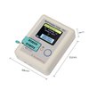
Have a look at one of these multifunctional component testers. These come in handy for such purposes (they may not be a hallmark of precision, but way better than guessing).
the HC-SR501 has a 1K resistor in series with the output
O.K., this escaped my attention.
 
The Edit button is there for the most recent post but disappears once someone replies to it.

I had to replace my venerable 100,000 ohm/volt analogue TVM last year and I thought it was pretty high tech that the new digital multimeter measures capacitance. Now I'm thinking about a multi component tester :rolleyes::cool::confused:
 
After debating for a couple of days I ordered an LCR-T4 tester. It arrived today and I'm disappointed. It looks like a really neat item but the display was damaged in transit. The seller is going to send a replacement but I'll have to wait a few weeks before I get to play with it :(

40 years ago devices like this were science fiction and the the idea of it being cheap enough for the average home experimenter to afford was a pipe dream.
 
Um... I bought the one Harald linked in post #21 from an eBay seller but as I said it arrived damaged so I'll have to wait for a few more weeks for the replacement.
 
Top