Maker Pro
Maker Pro

9v Guitar Amp w/out LM386

Referring to the initial A schematic submitted by DAVENN you can see the treatment for the base bias acquisition for Q3 transistor.
Then there is the B schematic ,which I know not where it came from, and you build up the unit using that schematic. You can see the B's different treatment, where there is but a single resistor being used to get its base bias.
Considering how well B worked with overall gain and musical voicing.
Disregard the proper biasing ratio as was in A schematic and dump R5 and use the 100K solo.
This circuit has always been seen with the speaker going to ground from the center point of the two output transistors paired emitters.
And as mentioned, when idle, that shared emitter voltage will be right at 1/2 the supply voltage, so that both + and - peak nodes of incoming audio can get equal gains before any peak compressions set in or progressively advancing on into flat topping occurs.
 
Ok so I've made a few tweaks (I think 500mA is a good starting point for guitars). I've upgraded to a 12KΩ to account for the higher AC source and removed those resistors (R5 & R6) but I'll keep them in mind in case I get into a pinch. I'll be back in the shop tomorrow morning and let you know how it went!

EDIT: Can't wait, going back to the shop now.

Finished9VAmp.jpg
 
Last edited:
You do not show any transistor part numbers.
The 470μF output capacitor reduces the output at 40Hz. Use 2200μF for frequency response down to 40Hz to be almost flat when the speaker is 8 ohms.

Maybe your peak input is 500mV, not 500mA. With your schematic in my simulation then the top and bottom of the sinewave is clipping. It is fine with an input of 450mV peak.
 
Thanks AG, I've just completed the circuit. I was forced to use my 2N2222/2907s until the mail comes in with the parts cited in your diagram. I've also got some 2n3053/2905As in the mail so I'm interested to see what I can do with those. In terms of amplitude, your circuit modifications make it wicked loud! Thanks! I jammed out with it until the transistors gave out (about 5 minutes) but I loved every moment of it! All I have in terms of transistors at the moment:
  • 4401/4403
  • 3904/3906
  • 2222/2907
I'll check back in with you guys when the mail comes and I've a chance to produce some more samples. It was a little crunchy, but barely. Although you predicted this already so again, no surprises there. Here's where I left off.

AG circuit almost.jpg
 

Attachments

  • AG circuit almost.jpg
    AG circuit almost.jpg
    317.5 KB · Views: 79
You are using weak and old transistors. The solderless breadboard and alligator clips also might not be able to pass the current.
 
Here is what I am seeing on the post # 52 breadboard wiring.
You have effectively wired it up in the exact manner which we wanted to see, with the speaker going to ground this time .
You are still using the same 100 K resistor for the biasing of the whole DC series string , but the only way that the unit is operating now is due to leakage thru the newly added 47 ufd electrolytic. (which is now installed with reverse polarity ).
By now, you are probably / and / additionally looking for the overlooked / omitted output transistors shared emitters wire in.

Sir AG . . . . .since you are already all set up, would you plot an analysis, omitting the 47 ufd cap . . . But using the same AF input LEVEL ?
Will add more later, but now, I'm stuck out at the mule barn on a Kindle.

73's de Edd
 
Last edited by a moderator:
Sir AG . . . . .since you are already all set up, would you plot an analysis, omitting the 47 ufd cap . . . But using the same AF input LEVEL ?
73's de Edd.
Bootstrapping strongly reduces distortion, increases maximum output level and increases gain.
I show it with the same input level but with and without the bootstrap capacitor. Then I show the distortion caused when the input level is increased but the output is not clipping yet.
 

Attachments

  • with and without boostrap capacitor.png
    with and without boostrap capacitor.png
    36.9 KB · Views: 68
  • without bootstrap capacitor.png
    without bootstrap capacitor.png
    26.1 KB · Views: 98
Hmmmmmmm. . . . . . Still out in the boonies .
But I guess it is just being the mag and chromaticity capabilities of the Kindle.
With my closest other color banding reference of a resistor( physically larger) being the 10K over at the adjunct AF input circuitry , but don't tell me that is being your mentioned 12 K Br-Re-Or . . . . . NOT.
BUT do now check the now 160k bias derivation resistors top lead, up to it's possible cluster of 5 connections and then compare total connections found, to the schematic.
But . . . . . ." Don't Panic! "

Mee what I Sean ? . . .Whoooooooooops . . . now . . . MY dyslexia's a' kickin' in.

73's de Edd
 
Last edited:
Sir Don Perry . . . . .


Nope, that's too young . . .I'm upping to15-25-35 yrs of age

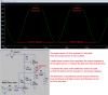
The units 9VDC supply is originating at the top left corner of board via a RED wire.
Power passes down from that point, via a 330 ohm resistor to the blue 47 ufd capacitor.
That lead of the blue 47 ufd capacitor branches off another 330 ohm resistor which passes over to the right, to the collector of Q3 2222A transistor.
Since this connection is the positive most node of the circuitry the 47 ufd electrolytic should have its + connection being made here and its - connection being the bottom connection.
You have it installed with reverse polarity.

Then, there is the 160 K*** ohm bias derivation resistor that has its top lead coming up and going to the bottom right lead of that capacitor.
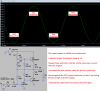
Now whichever way you installed that electrolytics polarity, it should STILL let a maximum need of up to 57 microamperes of current pass through it, to provide bias for the whole DC coupled transistor trio.

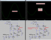
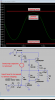
NOW check the connections found at the junction that we are now examining. Comparing what we have . . . . .know what ? . . . . you have no wire running over to the Q1 and Q2 shared emitters junction.

*** With a 32" HI Def. SUNNY Bravia monitor and being magged up to 800X . . ..I still read 3 band as black . . .but we know differently.

Now with my few given cryptic clues of:

"cigar box" + "transistors only" + " 9V battery power " + [ a small speaker, I'm gathering that as being 64Ω ] + Daddy Warbucks having commissioned you to do this task + you are being associated with a full blown music recording studio.

I will post my suspicions of the end result tomorrow.

BTW the choice of the 2N2222 and 2N2907 companions relate to the workhorse of reliability tested transistors that are HEAVILY used in military and aerospace .
The next step ups in power levels are the 2N2218A for the little brother 2N2222A and the 2N2905A for its little brother 2N2907 both of the heftier TO-5 metal housed transistors handle 800 ma when utilizing a screw on, finned, top hat heat sink.
With you playing mostly non sustained notes, and running through the spectrum I don't think that heat will be a problem.
PLUS . . . . . using as a plain guitar strumming function will never see any frequencies lower than an open E strings 80~ .

73's de Edd
 
Top