.
Sir Nauman Muhammad . . . . . . .
Behold . . .herewith . . . .is your comparative board referencing . . .as being derived from those GOOD photos which you supplied.
Far right is the boards components layout
In the center is a minimally touched photo . . . to use for foil path comparison
At the far left is component overlays to foil path solder points.
Looks like the far left photo is showing you that the AC power from your side mounted power transformer is bringing in
AC voltage thru the interconnecting two grey wires.
The four large diodes just above, converts that AC to DC voltage and the large 2200 ufd capacitor just above,
smooths out any pulsations in that initial DC to being almost battery quality pure DC at that ORANGE buss
lines point of origin.
Power then flows up through two series isolation diodes, D101-D102, and ends up at Terminal YELLOW C of the power relay which functions for switching between use of AC line or Battery power.
Still referencing to the far left photo, the Battery path has its NEGATIVE buss coming up and ending up as a shared common union with the AC lines DC power ground.
The Battery Positive path passes up and is connected to Terminal YELLOW B of the power relay.
Now that Power relay is energized by its internal coil winding being assigned as YELLOW C1 and C2 as identifiers.
If you look at the relay coil winding, you will see that the C1 terminal goes up to the collector of Q103 transistor.
The power relay is activated if the control transistors base . . .control buss line . . . receives activation voltage from the 5 wire connector . . .top pin. . . .Yellow wire .
Now in looking at the companion YELLOW C2 coil connection, it is receiving DC power from the R101 22 ohm resistor, which in turn gets its power from the ORANGE DC buss.
Sooooooo that means that the unit should have the relays YELLOW A to B contacts closed when there is no power relay coil activaton.
If AC power is coming in to create the other DC power source, then the relay can opt to select that sources DC power by relay coil activation and the relay contacts then being made from A to C contacts.
PRELIMINARY TESTING:
Lets now totally disconnect that unit from AC power and I guess that the battery's have slide on connectors,
so that the unit can be totally devoid of any Battery power also.
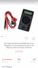
Time to use your new meters OHMS function.
Put it in OHMS, at its lowest range.
Short the test probes together and read the metering, now you know what a very low ohmmage or a short reads as.
Separate the probes and look at the metering, now you know what an open circuit reads as.
Take R101 which is a 22 ohms red- red- black and read across it . . . .figure out its reading manner on the metering until you interpret that shown reading as being ~22 ohms.
Move up to R109, just above, and see if it doesn't read as 33 ohms . . .since it looks to be orange- orange- black to my eyes.
Move over to R110 and see if it doesn't read 1 thousand ohms brown- black- red, you may have to click up once or twice on your meters ohms range in order to properly read this larger value of resistor.
Move up to R111 and see if it doesn't read 10 thousand ohms brown- black- orange, again, you may or may not have to click up once on your meters ohms range to get the optimum reading on this one.
These were considering that adjunct parts were not shunting those resistors and creating erroneous readings . and I didn't particularly see any present.
If so encountered, one needs to un solder and lift one resistor lead out of circuit.
Now I have you all warmed up to test one suspicious part . . . . basically just to see if it was not burnt open.
Down below your power relay and the white power resistor is L101 and it has a darkened heat stress ring showing around it.
Get in low ohms scale and read it to see what its expected low ohmmage is being . . . . .or if it gives that open circuit reading, which you familiarized yourself with, earlier.
New task:
At right top corner component side of the board:
You see your power feed to your fan, down below that you will see a light brown disc ceramic capacitor-a black electrolytic capacitor-and a black ferrite based inductor . . . all associated with "trash filtering" associated with that DC fan motor.
NOW . . . FINALLY . . . just to that inductors lower right is diode D109 . . . . it is also showing being heat stressed . . . . test across it to see if it is shorted, as was shown on your very first ohms familiarization.
FURTHER INFORMATION NEEDED :
Looking up from the missing fuse holder there is a U101 IC which I need the number of . . I am expecting it to be a low power three terminal regulator . . . akin to a 78L05 0r 78L08.
While in that area, I see that you have a short WHITE wire from one side of the board to the other . . . I don't think it is being NEEDED..
Consult center foil photo.
The battery negative / ground buss passes up to where you have a WHITE wire loop jumping the fuse connection.
The ground buss branches off to the right and continues (****) as a foil devoid path ,until where it passes up to the point where you see the copper start again.
That copper path to the left and then up to the area where you had the other end of that wire connected, looks to still be completely intact, so that side to side jumper wire should not be needed.
BUT you do need the longer white which brings your battery ground buss up to that area, due to the vaporized foil path.
(***) Dear 'ole DAD . . .you just gotta LOVE him . . . .as he was just TRYING to keep the family COOOOOL.
Somehow ? he just got his ups and downs and rights and lefts and fronts and backs and plusses and minusses of the battery pack confused.
That resulted in that massive instantaneous battery power being applied across that short foil path.
The foil sheds its resist, then goes to a cherry red colorization, makes BIG flashee-flashee in converson to a gaseous state along with sharp fast BANG.( Just like lightning and thunder ! )
In the interim. he is hopping from one foot to the other , peeing pants, and trying to . . . . make it STOP !
I see I gotta stop now and go pick up Gr-Grand daughter . . . will have to continue explorative saga tomorrow.
THE . . . " Board" : . . . . . . ( It Mags up . . .WAY-WAY . . .'mo bigger ! )
73's de Edd
.
.jpg")
.jpg")
.jpg")
.jpg")
.jpg")


")
