Maker Pro
Maker Pro

Wireless trigger for LEDs and buzzers

okay so I started a project and decided I needed a header file that would define everything like the port definitions and such (am I right in that being a header file or is that a include file???)

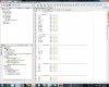
I tried to use the 'add existing item but that let to weirdness so I just created my own header file and copy and pasted this information that I found in a microchip folder. I have attached some pictures to show what the file looks like.

At the top it says "LIST" then on line 9 "NOLIST". are these reserved syntax words, what do they serve? am I going about this the right way? When I tried to comment out lines 1-43 all of the previously okay definitions (lines 50+) all got flagged as "unable to resolve identifier"

Some useful information might be that when I first created this project using MPLABX v1.90 I told it that I would be using a pic16f84, is my issue that I'm trying to define words ithat were previously defined?
 

Attachments

  • part1.jpg
    part1.jpg
    95.4 KB · Views: 118
  • part2.jpg
    part2.jpg
    92.7 KB · Views: 118
  • part3.jpg
    part3.jpg
    91.9 KB · Views: 100
  • part4.jpg
    part4.jpg
    90.9 KB · Views: 141
  • part5.jpg
    part5.jpg
    92.2 KB · Views: 106
I would suggest you to use XBee and Arduino.

You won't believe how easy is to start up and get addicted to these things. Buy for instance this book Building Wireless Sensors Networks

It even has exactly what you want to do. It explains how to do it, what items to buy and basically where to buy them.
 
Last edited:
Okay sorry guys for the delay between when I started this and how much progress I've made. I was so used to coding in assembly and my C syntax was rusty (close to nill) so I had a lot of catching up to do.

I was reading up on structures and unions for C programming and oddly enough my programming teacher never taught us this stuff (weird eh?)

So after a bit of reading I now understand what 'PORTBbits.RA0' and the like means. So now I feel like the steepness of that learning curve is out of the way I can actually start programming this damn thing.

I'll keep posting my updates

CHEERS!
 
a little update:

I didn't realize at the time since I was in the store but these PIC16f84's don't have an internal oscillator or PWM. Since then I have purchased a handful of PIC16f627a's and have finally got started.

I was configuring timer0 but didn't see a 1:1 prescale setting. Am I correct in thinking that just giving the WDT the prescaler that I can accomplish this?
 

KrisBlueNZ

Sadly passed away in 2015
Yes, this seems pretty clear from Figure 6-1 in the data sheet.

When PSA is set to 1 (i.e. the prescaler is being used as a postscaler for the watchdog timer), the selector to the left of the "SYNC 2 Cycles" block selects the output of the T0CS selector directly.

When PSA is 0, this signal (marked "TMR1 Clock Source") goes through the prescaler/postscaler and PS2~0 selector, then back up to the selector for the "SYNC 2 Cycles" block.

So setting PSA=1 gives no prescaling, i.e. divide-by-one, for the timer0 clock input.
 
configuring

Hey guys,

So working on the configuration of my PIC. now this is not how it will be configured once I get to working on the wireless transceiver, I just wanted to know if when configuring registers, ports, etc if a function call is the industry norm....or am I just wasting time? Here's what my configuration looks like so far


#include <xc.h>
#include <pic16f627a.h>
#pragma config MCLRE = OFF
#pragma config CP = OFF
#pragma config WDT = OFF

//function prototypes
void configreg(void);

//ignore this for now, will end up being pwm
int total_ime=0,on_time=0,off_time=0;

int main (void)
{
configreg();
}

void configreg(void)
{
//pullups diabled, internal clock, 1:2 timer0 prescaler
OPTION_REG=0x80;
//global interrupts, timer0 int enabled
INTCON=0xC0;
//port A inputs
TRISA=0xFF;
//port B outputs
TRISB=0x00;
//4 MHz oscillator
PCON=0x0B;
//timer1 off
T1CON=0x00;
//timer2 off
T2CON=0x00;
//capture/compare/pwm off
CCP1CON=0x00;
//turn comparators off
CMCON=0x07;
}
 
I've been having issues with my setup. All I'm trying to do is turn on an LED (there is commented-out code to make it blink) but it works intermittently, sometimes not at all.

My setup:
- PIC16f627a with a PICkit2 programming in circuit
- LED and resistor coming out of RB5 and going to ground
- Aside from the wires connecting all of the PICkit pins to the PIC16f627a nothing
- I don't have a pull-up resistor on the master clear but I turned off the master clear option in the pragma setting (does that matter?)

Are there special considerations when programming that I'm over looking? I've done this before with MPLAB coding in ASM with no problems but since the switch to MPLABX v1.85 and xc8 I'm having issues

Also, at first it was working, but when I implemented the blinking part the timing was off, not constant, then stopped working. Did I break something?
 

Attachments

  • Untitled.jpg
    Untitled.jpg
    90.4 KB · Views: 85
The default configuration for the PIC16F627A is to use an external RC oscillator. You need to set the FOSC config bits to select the internal oscillator.

Bob
 
The default configuration for the PIC16F627A is to use an external RC oscillator. You need to set the FOSC config bits to select the internal oscillator.

Bob

so I can just leave out the pragma setting where I configure the FOSC and everything should be okay?
 
oooooooooooookay I see what I did. I had it configured to

#pragma config FOSC = INTOSCCLK

but it should have been

#pragma config FOSC = INTOSCIO

since I wanted to use the internal oscillator. I would then assume that the intermittent blink of my LED was do to with me having nothing on the CLKOUT pin, so the PIC couldn't produce a steady pulse since it didn't have the required RC combination to work with
 
Okay I've got I/0 and some timing stuff down, next I'm going to get familiar with interrupts, then serial communication then this thing shall start taking shape
 
Okay guys so I bought this

To me it looks like it's just the NRF with a crystal and associated resistors/caps. I can't seem to find a datasheet for this particular breakout board. I should just be able to follow the NRF datasheet and be fine right?
 

(*steve*)

¡sǝpodᴉʇuɐ ǝɥʇ ɹɐǝɥd
Moderator
Google for NRF24L01 and the type of micro you're using and you'll. Find explanations code and datasheets.

Beware that there are 2 versions of this board. One has 10 pins, the other 8. The pinouts obviously differ.

If you really have trouble, I can have a look for you when I get to a device with a real keyboard :)
 
So I found this and came upon this:

"The SPI pins are all done, so now let’s get to the seventh pin from the top, the
IRQ pin. This guy is basically the interrupt pin to signal your microcontroller that
something interesting has happened. You can set interrupts for any combination of the
following events: data received, data transmitted, and maximum number of transmit
retries reached (this particular one is related to the 24L01’s hardware link-layer, more on
that later). If you’re not using interrupts, this pin isn’t required because you can poll the
24L01’s STATUS register over SPI to see if any interrupt has occurred, but it’s still faster
(in general) to check the status of an IO pin than to send an SPI command and then wait
for the response. NOTE: the IRQ pin is ACTIVE-LOW. It is normally high, but when
an interrupt is asserted, the pin will go low."

Could I use said IRQ pin to wake my uController from sleep or would that cause issues with the data that is being sent since it takes a moment for the uController to wake up or is there some sort of buffer area where the message is kept?
 
On another note I realized that my PIC16f627a does not have an SPI hardware module so I will have to most likely use a built in function. As I have never used it before I may start asking questions. Is anyone familiar with it?
 

KrisBlueNZ

Sadly passed away in 2015
Yes you can use the interrupt signal to wake your microcontroller up. But do you intend to use any power-down features? Is it important? Because it makes your code design somewhat more complicated.

An interrupt can wake the microcontroller, but in this setup, the interrupt handler should not do anything other than setting a flag (if necessary) and returning to the mainline. It can't initiate a new message communication with the device, since a message exchange might already be in progress. The interrupt notification needs to be integrated into the main code flow, so it can be handled at an appropriate point in the main code.

I would avoid using a power-down mode unless there's a good reason for it. It might be helpful to have the device's interrupt output connected to a digital input on your micro though, so your main code can poll it (at an appropriate place) to quickly detect that the device wants attention.

Bit-banged SPI is pretty straightforward but I'm not familiar with the functions provided in your library, whatever it is. In the unlikely event that you have problems, I'm sure that I, or someone else here, can help.
 
Top