Maker Pro
Maker Pro

VDO Voltmeter

I have a 6v vintage car. I want to add a voltmeter under the dash but 6v voltmeters are scarce. So I thought to add a voltage doubler inline before the gauge and adjust the gauge for any voltage loss. I’ve built a voltage doubler with a 555 chip and some bits and pieces. The doubler seems to work perfect on the bench with my multimeter. With a 6v battery and the doubler, the multimeter reads 11.5v. With a 9v battery and the doubler, the multimeter reads 17v. The car has a 6v generator and puts out around 7v which measures 12v with the doubler and using the multimeter.
Using the VDO gauge I get unexpected results. Not using the doubler, VDO reads the voltage correctly, 12v battery reads 12v. 9v battery reads 9v. However when using the doubler I get very low results. 6v battery and doubler read 8. 9v battery and doubler reads 11v. So my 7v car generator doesn’t barely register on the VDO which starts at 8v. So... why does the doubler show different results between the multimeter and the VDO gauge?
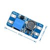
 
Quick guess would be extra current required by the analogue VDO voltmeter compared to digital multimeter?
Connect both the voltmeter and multimeter to the doubler, and then check the voltage reading on the multimeter.
 
Quick guess would be extra current required by the analogue VDO voltmeter compared to digital multimeter?
Connect both the voltmeter and multimeter to the doubler, and then check the voltage reading on the multimeter.
When I do that, the multimeter reads about 8v. When I disconnect the VDO, the multimeter jumps up to 11v. Is this result suggesting that I can’t use an analog gauge with this doubler? Do you have a suggestion?
 
Ah..ok....m
My understanding about these converters is that it outputs a constant higher voltage. I want to double my varying voltage. Am I wrong about that?

Ah...ok....misread on my part.
Will think a bit more on it.

If it is basically a current issue then boost the handling ability with say a mosfet for example.
Show us a circuit what you presently have.
 
Last edited:
Can't you use a 100μA meter that looks the part and put a resistor in series with so that it reads the correct voltage. It would save all the messing about with voltage doublers.
 
Can't you use a 100μA meter that looks the part and put a resistor in series with so that it reads the correct voltage. It would save all the messing about with voltage doublers.
My goal is to use a gauge that looks proper and that would be a vintage VDO gauge. With that said, there are only 12v gauges available. I need to have a 12v gauge work with 6v input voltage, so I assume I need to double it. If you have another way to meet these requirements, I’d love to hear it. Thanks.
 
All voltmeters start life as a current meter. They just have a resistor in series with the armature coil so that it takes a certain voltage to develop the required current through armature coil for full deflection.
If you could get inside whatever meter you choose to use, you should find a resistor of some description in there. That resistor value could be adjusted to give the correct sensitivity that you require.
If you can't gain access, measuring the resistance of the meter would be a start.
 
Further. All IC's require a minimum voltage to function correctly below which they will either not work at all or produce very erroneous results.
A 6V battery could easily drop some way below it's nominal voltage meaning any circuit designed may not function at all or at best incorrectly.
 
All voltmeters start life as a current meter. They just have a resistor in series with the armature coil so that it takes a certain voltage to develop the required current through armature coil for full deflection.
If you could get inside whatever meter you choose to use, you should find a resistor of some description in there. That resistor value could be adjusted to give the correct sensitivity that you require.
If you can't gain access, measuring the resistance of the meter would be a start.
Looks like this inside. One big resistor like you said and there’s also a diode too. Can I replace that resistor with some sort of potentiometer so I can adjust the resistance?
 

Attachments

  • 256D8336-03A7-440F-89C8-1763A17CE0C9.jpeg
    256D8336-03A7-440F-89C8-1763A17CE0C9.jpeg
    57 KB · Views: 8
  • 814D6F79-8861-4476-A004-F7C741BB7AEB.jpeg
    814D6F79-8861-4476-A004-F7C741BB7AEB.jpeg
    298.2 KB · Views: 9
68.1Ω @ ±2% seems a bit odd. It could be anywhere in the range of 66.8Ω to 69.2Ω so the 0.1Ω bit would be a bit superfluous not only that but 68.1Ω seems quite low as well.
If you have a DMM, could you measure the actual value of the resistor?
 
68.1Ω @ ±2% seems a bit odd. It could be anywhere in the range of 66.8Ω to 69.2Ω so the 0.1Ω bit would be a bit superfluous not only that but 68.1Ω seems quite low as well.
If you have a DMM, could you measure the actual value of the resistor?
I can’t measure the resistance without taking it apart. I will do that but it’s a process. Meanwhile I tested the voltage drop from the resistor, 12v in and 2v after the resistor. Assuming 68ohm R, I think I’ll need a 27ohm R to drop 6v to 2v. I should know more after I take it apart. But thinking that a 27ohm 1W resistor is the answer???
 
Hello,

I would give an other value.
680 Ohms 5% 50 ppm

View attachment 50879
Bertus
I know absolutely nothing about resistors except what I’m looking up on the web so I’m likely wrong. This resistor has 5 bands so the first 3 blue grey brown = 681 and then the gold multiplier = .1, so 68.1ohm total. Please tell me what you see. I’ll know for sure when I get the resistor out. Thanks.
 
Hello,

It depends on wich standard for the color code is used.
The table I posted uses a colorband for temperature stability according the EN60062:2005 standard.

Bertus
Ok. Don’t understand why the differing color code tables. This resistor is circa 1975. And like I said, I should be able to test it when I get it out. Thanks.
 
Top