Maker Pro
Maker Pro

using bjt amplifier to obtain a current higher than the maximum current an arduino can output

Hello,

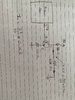
I need to output a current of 0.16 A from an Arduino uno , but the maximum current the Arduino can output is 0.06 A so I thought about outputting a certain voltage then using a bjt amplifier to amplify it and then add an output resistance to control the current flowing through the output, I did all the calculations as shown in the image :
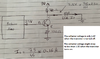
the voltage gain of the bjt is : A = 300/100 = 3 so if I output 2.5V from the Arduino I should obtain Vo = 7.5V.

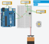
, but when I simulate the circuit, (I checked all the connections they are correct and I indeed have 2.5V in the arduino output) I get Vo = 2V instead of 7.5V I thought about this a lot but I can't seem to find where the problem lies so If someone could help me out with this I would appreciate it a lot!
 

Attachments

  • circuit.jpg
    circuit.jpg
    226.1 KB · Views: 15

bertus

Moderator
Hello,

I mean as series resistor between the arduino output and the base of the transistor.

Bertus
 
I did this as well but when I stimulate this I get no current flowing through the collector as shown in the image
 

Attachments

  • circuit.1.PNG
    circuit.1.PNG
    107.4 KB · Views: 10
Are you trying to supply 160mA into your load at a terminal voltage of 7.5V or is it meant to be a constant current and that the 7.5V is just a result of that specific current flowing in your load?
 
Simple Ohms law says that for 7.5V into the 46 ohms load then its current is 7.5/46= 163mA. The 163mA in the 300 ohm resistor needs 163mA x 300= 48 9V. Then the supply voltage must be 7.5V + 48.9V= 56.4V plus the 1.8V at the emitter of the transistor = 58.2V.

Without the load but with a 9V supply then with a 2.5V input, the emitter will be 2.5V - 0.7V= 1.8V and the emitter current will be 18mA which will also be in the 300 ohms resistor which will have 18mA x 300= 5.4V across it. The total is 1.8V + 5.4V= 7.2V so the 9V is too high.
 

hevans1944

Hop - AC8NS
Bye, bye, @abder!

It appears you are one of our infamous drive-by posters who leaves when an immediate answer to their problem is not forthcoming. I say this because you have not responded to a dialog offered by @WHONOES and @Audioguru. Perhaps you were put off by @Harald Kapp's suggestion in his post #7. Perhaps @bertus' two attempts to help you convinced you that this was not the right place for you. Or, perhaps, the brown-black-white (10,000,000,000 Ω) gold (5% tolerance) resistor shown in the collector of your transistor in your post #5 limits the current to a value too small to show in your "alleged" simulation?

I did this as well but when I stimulate this I get no current flowing through the collector as shown in the image
Yep, a 10 GΩ resistor will definitely "simulate" virtually zero current. A real 10 GΩ resistor is likely to be a glass-encapsulated rarity that you will probably never encounter. The glass is there to prevent a shunt path around the resistor. Such resistors require special techniques when inserted in a real circuit to avoid "shorting out" their extremely large resistance values. This is a major problem working with simulations instead of real components: how do you know the simulation is representative of the "real world" unless you build with real components? BTW, 10 GΩ resistors may also be used in high-voltage applications, upwards of a megavolt or so, but they are large and often surrounded by SF6 insulating gas at a hundred or more atmospheres of pressure... again, not something the average electronics enthusiast is likely to encounter.
 
Top