Maker Pro
Maker Pro

Trying to buy the right sockets for my PICs

Hello everyone!

I have a beginner question.

I've been trying to buy IC sockets so I can easily move my PIC chips around.

I think I should be buying DIP sockets, with 2.54mm pitch, and 7.5mm row to row spacing, correct? (For the relevant number of pins of course).

There seem to be numerous sockets around. Very confusing. I tried searching on Mouser and there are numerous listings for such sockets.

The photos don't seem to match the specifications either.

Any caution or other advice? I don't want to end up with a bag of sockets that are the wrong sizes.

I want to get sockets for my 18, 20, and 28 pin PICs.

Thanks.
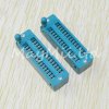
Yes, 0.100" pin spacing by 0.300" (7.62 mm ?) or 0.600" width is standard for DIPs. Yes, there are other standard sizes. I imagine PICs come in those also. Personal preference for me is Machined Contacts as opposed to side wiper kind. They cost a little more but if you are going to change them often they are worth it.
For very high use, like in programmers, Zero Insertion Force (ZIF) designs are best.
 
ZIF sockets are absolutely the best. The only drawback, they don't go well into the breadboard, so intermediary PCB is needed for breadboarding.

s40pin.jpg
 
Thanks for the ideas. I have a ZIF for one of my PIC programmers but did not consider them for the final circuit. Might be pricey?

Regarding "Machined Contacts" do you mean the circular ones? I know there are "side wipe" ones that seem more like spring contacts. Is this what you mean?

Thanks!
 
Why would you use a socket for your final projects? I always solder mine in. I needed to replace on once and I did so by desoldering it and soldering a new one.

Also, you don't want to be moving them from a programmer to the final board. The time it takes is truly annoying and you will break a pin off more often then you want. Put a programming header on the final board.

Bob
 
I had read that by using a socket, you don't risk overheating the IC. Also, a socket is fairly cheap compared to a micro controller, so for simple projects you can just reuse the PIC when you don't need that project to be working at that time.
If you mean that one should program the PIC right in the final circuit, wouldn't the connections on the board interfere with the programming? (Even if you just attach jumpers from the PICkit to the IC pins).
 
If you mean that one should program the PIC right in the final circuit, wouldn't the connections on the board interfere with the programming? (Even if you just attach jumpers from the PICkit to the IC pins).

Unless the PIC is very small, in-circuit programming/debugging is the best way to go. With the small ones (such as 6-pin), its' not very productive - you don't want to give up 3 out of 4 available pins for debugging.
 
The PIC microcontrollers do not get hot unless you have done something wrong.

ICSP uses two pins, but you can, with a little forethought, use these same pins in the circuit. Just don't use the pins as outputs that control something you do not want to have a signal on while programming. If they are connected to an LED, it will flash during programming, which is actually kind of cool!

For the 18 pin and 24+ pin pics, (but not the 20 pin ones for some odd reason) you can dedicate 2 pins to use for debugging. Once you get into it, you will generally want to do this anyway.

Oh, and the sockets do cost as much as some of the PICs. PICs come as low as 50 cents.

Bob
 
OK thanks. I bought some PICs for several dollars EACH (e.g, PIC16F84A, PIC16F873A, PIC18F2420). Will look into the cheaper ones. And also in-circuit options.

By the way I was not referring to running the chip hot. I meant soldering. In fact I read about this from several authors including Steve Wozniack (to solder in the sockets first, then press in the chips).
 
OK thanks. I bought some PICs for several dollars EACH (e.g, PIC16F84A, PIC16F873A, PIC18F2420). Will look into the cheaper ones. And also in-circuit options.

These PICs are overpriced because they're old and not mass-produced any more. They also have a number of problems, which have been solved in newer ones.

For PIC16, look at the PICs which number starts from "PIC16F1" (or "PIC12F1" for smaller ones). There hasn't been any new PIC18 for a while, but the ones with letter "K" in the middle are newer and better. If you want something more powerful, then instead of PIC18, look at PIC24/dsPIC33. There are also PIC32 series, bit IMHO they are not suitable for a beginner.
 
Thanks; those are old chip but the books I have to learn about PIC are also not the newest. I will try to see if there are any compatible newer chips with the same instruction sets. I just didn't want to get confused. It's already confusing because MPLAB has been updated so the UI has changed. Even the tutorial docs from Microchip can be different from the latest MPLAB/LAB-X release! Not easy to learn for newcomers unfortunately. Slowly getting there with help from others like yourself, and watching YouTube.
 
Last edited:
in-circuit serial programming (ICSP) for PIC microcontrollers is designed just for such uploading into the PIC in the final circuit. There are a couple of precautions to take however. In terms of PICkit programmer, it provides target Vdd (5V) during programming and the MCLR (pin 1) is the programming voltage which is generally 13V. A diode is needed to prevent the ICSP high voltage from interacting with the power supply circuit. The signals on the PGD and PGC lines transmit the actual programming to the PIC, and since the PIC pins (generally port B pin 6 and 7 for the 18F and 16F series) are also general purpose I/O lines, it is recommended that these are isolated from any attached circuitry during programming. This will avoid the PICkit (or other programmer) attempting to power-up such circuitry. Similarily, since the PICkit provides the target Vdd, the PIC Vdd is also isolated during ICSP to stop any potential interaction with the power supply. This can be done simply with jumper links (or switches are more convenient on a development or prototyping board).

Have a look at the following for a schematic, more details http://www.fadstoobsessions.com/Electronics-Projects/DIY-Tools/DIY-PIC-Dev-Board.php

That website is awesome BTW. Thanks.
 

CDRIVE

Hauling 10' pipe on a Trek Shift3
By the way I was not referring to running the chip hot. I meant soldering. In fact I read about this from several authors including Steve Wozniack (to solder in the sockets first, then press in the chips).
Presumably, those must have been authored by people that either solder like a welder joining 1/2" thick I Beams or have little faith in the abilities of others to not fry what what they're soldering.

Chris
 
Top