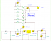
So if it states in the schematic above that each base resistor current is about 138 mA , with the TIP2955's, then the base current will be 1% of that for each base junction. Will the 100 ohm base resistor in the circuit above still be ok to use for the MJ11015 transistors. Would it still bias the transistor to switch on and carry the current, and keeping the regulator current to about 800 mA as in the circuit above. What I'm getting at really, would I need to change any resistors for the use of the MJ11015 transistors. Steve said above they should be fine. I only ask as I struggle a bit with the math. So the difference in current limiting the base of the MJ11015 transistor with the same rating as used for the TIP2955 transistor. I'm appolagies if its long winded, just trying to get my head round the maths with this more powerful transistor.
No, no, yes, no. Because the effective base-emitter voltage of a power darlington is about twice that of a non-darlington, R7 will have to increase to produce the necessary voltage drop to cause the power transistors to start conducting. The transistor gain is 1000 min at 20 A, and over 5000 at 5 A according to the plot. So the total base current is only 5 mA plus a few mA through the internal resistors. This is very small, and I think it can be ignored in terms of calculating how much current is going through the 7812. That current is set by the relationship between R7 and the overall Vbe of the transistor. The datasheet does not have a chart for Vbe as a function of anything, but a reasonable starting point is that it will be around 2 V, probably less. You also have to figure in the voltage drop across the ballast resistors.
The ballast resistor has two functions. It can be used to take some of the thermal stress off of its transistor. For example, if we have 5 A through each transistor and 15 V across it, that's 75 W. If the transistor is rated for 80 W, that's way too close to its limit. But if you put in a ballast resistor of 1 ohm, the resistor will dissipate 25 W, leaving only 50 W for the transistor to handle. The idea here is that a resistor is less expensive than a higher performance transistor, and also that a big fat power resistor is more reliable at high temperatures. There is a tradeoff, in that the ballast resistor reduces the input voltage range over which the circuit will function. But you have a relatively constant input voltage from the transformer, so that does not apply here.
The second thing the ballast resistor does is assure that the total power load is distributed evenly among the transistors. No two or five transistors have exactly the same base-emitter voltages or gain, so for any particular base current or Vbe the transistors will conduct different amounts of current. In an extreme case you could have 5 transistors in parallel, with four of them conducting 1 A and one of then conducting 26 A. Not good. With a resistor in each emitter leg, the total voltage in the base-emitter leg from one transistor to the next is now the individual Vbe plus the IR voltage drop across its ballast. If one transistor starts to conduct much more than the others, its ballast voltage increases, which decreases the voltage across its base-emitter, which decreases its gain, which decreases its conducted current. This is a form of negative feedback called degeneration. So, if you have a feel for how much the Vbe of your group of transistors will vary, you can use this to set a minimum value for the ballast resistor.
R7 = Vtotal / I7812, the total of all of the voltages in series across resistor R7 divided by the current through the 7812.
If we choose a worst-case 7812 current of 0.1 A, then the question is what is Vtotal at 5 A per transistor. The transistor circuits are in parallel, so their voltage drops do not add up for this. Let's pick R1 as the typical ballast resistor.
Vballast - 5A x 0.1 = 0.5 V.
Pballast = 5 A x 0.5 V = 2.5 W
Not a bad starting point. As above, you can increase the ballasts to take some power away from the transistors and get better load sharing among the power transistors.
Vtotal - Vbe plus Vballast = 2.0 + 0.5 = 2.5 V
R7 = Vtotal / I7812 = 2.5 V / 0.1 A = 25 ohms
The power dissipated in the 7812 is its current (0.1 A) times the differential voltage across the regulator minus the 2.5 V across R7. So if the average voltage on the big filter caps is 20.5 V (to make the math easy), then:
P7812 = 0.1 A x (20.5 - 12 - 2.5) = 0.6 W
And finally (!!!), this value of R7 is much less than the 100 ohms in the original design. That value had very little current going through the regulator to the load, something I don't think well of. Power regulators work best when they have something to chew on. My example increases the 7812 current significantly. It is up to the designer's discretion; there is no one "right" number.
ak