I am after a transformer with a 15-0-15 secondary at several amps. Yesterday a couple of transformers landed on my lap (luckily they didn't land on my foot). Unfortunately they each have a pair of 30V windings.
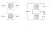
Can I connect the primaries in series and the outputs of the two transformers in parallel to give me a pair of 15V outputs?
I would pair up a winding from each of the transformers to maintain the same load on each.
The transformers are each rated at 300VA and are toroidal. I expect the combined output will be limited to 300VA in this arrangement (which is heaps).
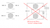
Please assume I can manage to get the phase relationship correct and that I'm aware that this is a very extravagant use of two expensive transformers")
Since both transformers are rated for the full input voltage, there shouldn't be any concerns WRT insulation resistance.
Can I connect the primaries in series and the outputs of the two transformers in parallel to give me a pair of 15V outputs?
I would pair up a winding from each of the transformers to maintain the same load on each.
The transformers are each rated at 300VA and are toroidal. I expect the combined output will be limited to 300VA in this arrangement (which is heaps).
Please assume I can manage to get the phase relationship correct and that I'm aware that this is a very extravagant use of two expensive transformers
Since both transformers are rated for the full input voltage, there shouldn't be any concerns WRT insulation resistance.