Maker Pro
Maker Pro

Thermocouple RF Ammeter

What is the characteristics of the thermocouple device used with a thermocouple RF ammeter? I have several meter movements labeled in RF Watts, but missing the probes. Are these typically J or K type thermocouples, or thermopiles? Or, are they shunts with a thermocouple attached? Do the meters measure millivolts based on the probe tip temperature as in typical thermocouple temperature measurement?

How do they work? Is the thermocouple placed in an RF field and heated by induction?
 
I think they work by passing the rf current through a wire and basically measure the temp rise of the wire. If you know the resistance of the wire and its temp you could work out the current. The thermocouple just measures temperature with a voltage output related to temperature. Not sure what type they use, I guess it depends how hot the wire gets, type K could be used for this as it has a higher operating temp than J types.
Adam
 

hevans1944

Hop - AC8NS
Please post a picture showing the type and brand of RF ammeter you have. Many of these have a built-in resistance and a thermocouple that directly drives a sensitive D'Arsonval meter movement. Here is a You Tube video showing the internals of such a meter.

It doesn't really matter what the thermocouple materials are. Type K thermocouples (chromel/alumel) are not necessary and have the disadvantage of relatively low sensitivity compared to type J thermocouples (iron/constantan). OTOH, type K are virtually immune to environmental factors, such as humidity, whereas iron does rust. For either type of thermocouple, the temperature rise above ambient at full-scale RF input current is small.

There are other instruments that use a "true rms" conversion based on an RF current heating a resistance-wire sealed inside an evacuated glass bulb. A very small thermocouple is welded to the resistance-wire to measure the increase in temperature as the resistance-wire is heated by the RF current.

The vacuum inside the glass bulb decreases heat lost to conduction through air, leaving only heat lost through conduction through the thin wire leads and radiation from the resistance heating element as the main factors affecting the thermocouple output as a function of RF current input. Even so, this transducer is highly non-linear in its response to RF power, so it is normally used in any of several bridge-balancing circuits over a narrow range of input currents. An accurate attenuator is necessary to reduce the RF input current to a range suitable for use with the transducer. The main (perhaps only) advantage of this approach to RF current measurement is that it allows comparison of an unknown RF current to a precisely known DC current. Note that the RF current does not have to have any specific waveform: the transducer is a true-rms converter that compares the heating-effect of an alternating current waveform to the heating-effect of a DC current, the latter presumably being precisely known and controllable.
 
@hevans1944 ,
I have never seen one such RF ammeter before.
It brings up the question what good are they for?
My answer,not much...
Maybe it was good for something in the 1920's when RF was something like 1Mhz and below.

Today we never care about "RF amps" .
We do care about "RF power" and that always involves the characteristic impedance (matched and unmatched)and the frequency.

I doubt that the op is referring to these moving-coil ( aka D'Arsonval ;)) meters.

He does say "missing probe" so I would think he is talking about analog "RF power meters".
The probes impedance being 50(mostly) or 75 ohm.
These have one of 3 sensors types in the probe:
1.Thermistor.
2.Thermocouple.
3.Diode

Agree about letting us know the type,a photo would be nice...
 
Example 1 is a GE 8DW52AA! Thermocouple Type RF Ammeter I found a good description on u-tub It has a built in thermocouple, and measures true RMS via heat produced.(independent of frequency). I believe this wo ld make it useful for measuring antennae current, for calculating radiation resistance etc. I was hoping to see some practical examples of connecting it in-line with a transmission line.

Example 2, is a Mc Intosh Electrical Corp, High Frequency Milliameter. It has to ranges: 5000, and 0-1000 Milliampres. I could not find any documentation. I believe this is a similar device but different name. Also,possibly, called a Hot Wire Ammmeter.
IMG_0872.JPG
 

Attachments

  • IMG_0874.JPG
    IMG_0874.JPG
    45.2 KB · Views: 199
  • IMG_0874.JPG
    IMG_0874.JPG
    45.2 KB · Views: 182
  • IMG_0874.JPG
    IMG_0874.JPG
    45.2 KB · Views: 159

hevans1944

Hop - AC8NS
Here is an image of a spiffy little "true rms" converter I acquired many years ago and have been a little bit afraid to play with. The two vertical wires are where you apply a current. The two little bent wires are thermocouple leads. Inside the glass envelope is presumably a vacuum. I have no idea where to obtain another one if I were to "let the smoke out" of this one. The smoke would of course be contained within the glass bulb, but that wouldn't do me any good.

upload_2016-4-1_17-36-9.png

At one time I actually discovered on the World Wide Web what the part number for this ancient device was... not that there was any chance of purchasing more of them. I think it might have been made by Weston Instruments, or maybe Western Electric. I am "pretty sure" it is a broadband true rms RF transducer, and maybe if I shined a laser or strong light onto the end of it there would be a detectable thermocouple output. If I can summon up enough courage, I will try to "activate" the resistance wire with a very low current and see if there is a measurable thermocouple output. For now it is just a obsolete curiosity and a remembrance of things long ago... This, or a similar device, might have been part of the probe that is missing from the OP's instrument. But as @dorke said, we now have "better" ways to measure RF voltages, currents, and power.

Still, the ability to go back to "first principles" has always fascinated me regardless of how many bells and whistles technology adds later. Measuring the heating power of an alternating current and equating it to the heating power of a DC current is practically the definition of rms current, and usually a lot easier to do than calculating (or measuring) the "root-mean-square" values necessary to find the rms value for an arbitrary and complex waveform... well until gigahertz A/D converters and gigahertz computer processors came along, now at "dirt cheap" prices. Has anybody seen what kind of real-time spectral image processing you can do with a scanned grating or a Fabry-Perot interferometer and a Fourier transform processor? Amazing stuff, and not just for astronomy anymore.

Hop
 
@hevans1944,
My main problem with that device is actually with it's name.
Calling this an "RF-meter" is kind of a joke.;)
Like I said in the previous post,unless we are in the 1920's when RF was something like 500Khz.

The problem with that device for measuring RF frequencies is there is no way to insert the device "as is" in a circuit to measure power or current without an error-ed result.
Inserting it will effect the matched characteristic impedance of the line it is inserted into thus strongly effecting the working condition of the circuit and getting a wrong measurement result.

The classical RF power meters of the 70'S (many Ghz and higher capable)
like the HP 432/435/436 relied on Thermocouples/Thermistors measurement without any fancy calculations... actually they had no μP at that time;)
 

hevans1944

Hop - AC8NS
@dorke: I have no idea how well it would perform at RF. It would certainly require some sort of matched attenuator to prevent it from "letting the smoke out" but, as I mentioned, I am reluctant to mess with it. The HP power meters used two thermistors, both DC excited in two separate feedback loops, but one exposed to RF power and the other not. This scheme allowed for ambient temperature compensation, but the meter still needed to be "zeroed" periodically. Clever analog processing (PAM and PWM) allowed the meter movement to "integrate" or average the RF power applied to the exposed thermistor. And yes, the thermistor mount provided a good impedance match to avoid interference from standing waves.

I am not sure where you got the idea that RF was limited to 500 kHz in the 1920s.
 
Thaught I would see what my RF Ammeter would read on a UHF CB into a 50 ohm dummy load. Working on RF = I squared x R, .23A current & 50 Ohm load was about 2.6 Watt. Reads a bout half what the transmitter is rated at. RF AMMETER.JPG UHF TRANCIEVER. 5W.JPG
 
Interesting discussion, thank you both.
Actually, I'm thinking you cannot get much more accurate and simpler than measuring heat produced to determinie RMS value. Frequency should have no bearing, aside to physical limitations.

In my youth I determined resonance of my transmitters via a dc ammeter in the plate circuit of the final output; looking for a dip. I believe the RF ammeter could be used in the same configuration but tuned for maximum output. If one knew the load impdance, multiplying the RF current indication would give a relatively accurate power output value.

I determined the GE RF ammeter is functional by putting a known DC current through it and comparing it to my Fluke True RMS DMM,

The Mc Intosh meter appears defective. I disassembled it : and it appears one thermocouple is missing, and one lead to the meter armature was burned off. I was able to replace the burnt lead; and got the meter movement working, but the missing thermocouple is a problem finding a replacement. I soldered a piece of wire where I think it should go just to see if I could get some meter action but with little success.

I find it odd they would use two thermocouples (one for each range). Possibly my schematic is wrong, maybe one was being used as a reference.

Here are some crude photo's and a rough schematic:IMG_0883.JPG
.
 

Attachments

  • IMG_0880.JPG
    IMG_0880.JPG
    38.7 KB · Views: 148
I like your vacuum tube contained true RMS device. From the photo it appears to be (3) wire device. Current in and current out, and sensor.

I'm curious. Does the sensor connection between the In and Out constitute two junctions or one.. Since only one wire is physically attached making a junction? In a K-type Nc/Na, would the current thru wire be Nc, and the wire to the meter be Na?
 

hevans1944

Hop - AC8NS
I like your vacuum tube contained true RMS device. From the photo it appears to be (3) wire device. Current in and current out, and sensor.

I'm curious. Does the sensor connection between the In and Out constitute two junctions or one.. Since only one wire is physically attached making a junction? In a K-type Nc/Na, would the current thru wire be Nc, and the wire to the meter be Na?
It is a four-wire device. It is hard to see in the first image I posted, but there are two wires exiting the device on the left side. Each end of the two wires is bent 90 degrees in opposite directions, more or less perpendicular to the heater wire running top to bottom. There is a paint mark next to one of the wires, probably indicating the positive TC connection polarity. With a magnifying lens, it can be seen that these two wires are welded inside the glass envelope to two extremely fine thermocouple wires that are then welded to the center of the much thicker wire that runs from top to bottom in the image.

I have no idea what the external circuit was, but the TC appears to be quite fragile, so not much (if any) current could be provided by the thermocouple. I also imagine the thermal time constant is rather long because of the relatively large mass of the heater wire compared to the thermocouple wires. Maybe one of these days I'll find the cojones to measure that.

I see no reason why this arrangement wouldn't be useful from DC to Light if you can couple energy into the heater wire, hence my earlier statement that I might try to "energize" it with a laser or a focused intense light source, hopefully without burning away the TC lead attachment. Since you can see through it, it obviously would absorb energy in the visible spectrum, but who knows how this particular glass envelope behaves in the near-infrared (which is the only band in which I could afford to purchase a laser diode with significant power)? Anyway, I keep it around as an example of measurement technology based on first principles. I have no idea what its RF bandwidth could be, but the dimensions imply that things would start to get tricky above 100 MHz or so. Back in the day, it was probably used to measure signals with frequency content no greater than 100 kHz, perhaps much lower.

upload_2016-4-2_13-47-56.jpeg
 
Interesting discussion, thank you both.
Actually, I'm thinking you cannot get much more accurate and simpler than measuring heat produced to determinie RMS value. Frequency should have no bearing, aside to physical limitations.

In my youth I determined resonance of my transmitters via a dc ammeter in the plate circuit of the final output; looking for a dip. I believe the RF ammeter could be used in the same configuration but tuned for maximum output. If one knew the load impdance, multiplying the RF current indication would give a relatively accurate power output value.
.

No way!
You can not use this "wire" to measure in an RF circuit.
Inserting it in an "RF-trace" will immediately create a severe disturbance in the RF transmission line creating a SWR which will change the working condition of the circuit.
This is a basic violation of any measurement instrument!

Furthermore, as you move the location of that "wire" along the transmission line you will have different measurements!

You should use a directional-coupler power meter like the legendary BIRD 43:
43p-1.jpg
 
I agree any device inserted along a transmission causes a bump in impedance. (Any). I too, have a Bird 43. It is a directional coupler and completely different in operation compared to an ammeter. An ammeter was typicaly used in the plate loading circuits of military transmitters .
 
Having trouble uploading files. I Tried to send a scan of page 512 of 1978 ARRL Handbook. The same text and photo appears in other handbooks. It clearly shows the same RF Ammeter (Same one I have) mounted in a Bud Box with a SO-239 Connector in and SO-239 connector out. The meter is in between.

Description is as follows:

Fig. 17-10. The RF ammeter mounted in a minibox, with connection for placing the meter in series with a coaxial line. A bakelite -case meter should be used to minimize shunt capacitance (which introduces error) although a metal case meter can be used if mounted on bakelite sheet with a large cut-out in the case around the rim. The meter can be used for rf power measurements (P=I sqr R) when connected between a transmitter and a non-reactive load of a known resistance.
load resistance for calculating the fr power delivered to the load.


from text:

............Thermocouple meters can be obtained in ranges from about 100 mA to many amperes. Their useful upper frequency limit is 100MHz. Their principal value in amateur work is in measuring current into a known resistance for calculating the rf power delivered to the load..................


The ideal setup is to put this in the transmission line between the transmitter and antenna tuner.
 

hevans1944

Hop - AC8NS
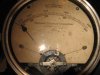
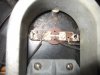
RF ammeters like the ones @Y2KEDDIE has, or the simple vacuum thermocouple attached to a heater wire as in the image I posted, are functionally obsolete, replaced by better technology. However, the first principle of measuring RF power by measuring the amount of heat it produces is always valid. Only the methods have changed, not the fundamental principle. Thermocouples are still very much a part of RF power measurements, as are square-law diodes and thermistor sensors. Here is a very thorough discussion of the state-of-the-art in RF power measurement, published by Agilent (formerly Hewlett-Packard), a world-class leader in RF power measurement instrumentation.

The Bird Model 43 wattmeter is a tried-and-true in-line RF power meter that, using a directional-coupler, measures forward and reflected power when inserted in a 50 Ω transmission line. But it is limited to CW measurements. The Bird has been the "gold standard" in both commercial and radio amateur practice since practically forever, but it too is rather primitive technology. At the this year's upcoming Hamvention® in Dayton, Ohio, there will be dozens of vendors offering Bird wattmeters and "slugs" for same... along with upcoming clone products.

The Bird is popular, not because it is particularly accurate and inexpensive (it is not!), but because it simply works. Many hams shun the SWR bridge, which is constructed using similar principles, and simply tune their rigs for minimum reflected power using a Bird wattmeter. Among hams, the forward power measurement is mainly for bragging rights, IMHO, because the type of ham who uses a Bird is usually aiming for maximum power output as compared to the ham who pursues QRP operation, or the "minimum power necessary for communication" as specified in the FCC rules for amateur radio.
 
I'm toying with the idea of making my own replacement thermocouple for my High frequency Milliammeter.. We use to make our own K types in the lab by twisting the thermocouple wire together and gas welding the junction. The theromocouple in the meter appears to be one type material for the current to pass through (KN) end to end, and the other type (KP) as a tap making the junction. Calibration should be easy, just use DC current and compare. Provided it is a K type!

The nice thing about the Bird 43, is it can be used at UHF frequencies. The problem is when sending UHF up a long feed line, the reflected power is ate up by the line losses, it appears all the (forward)power is going to the load and nothing coming back.
 
Last edited:

hevans1944

Hop - AC8NS
,,, The nice thing about the Bird 43, is it can be used at UHF frequencies. The problem is when sending UHF up a long feed line, the reflected power is ate up by the line losses, it appears all the (forward)power is going to the load and nothing coming back.
All the more reason to locate the watt-meter as close as possible to the antenna feed. It IS very portable. And make sure you are using the right "slug," Type D or Type E for UHF.
 
Top