Maker Pro
Maker Pro

Tesla coil driver mosfet problems.

The above circuit quickly frys mosfets at 60v power supply. At 30v and with a 300 ohm resistor replacing the 700 ohm resistor, it works well. Help please.
 

hevans1944

Hop - AC8NS
@Exidor: Are you SURE you posted a correct schematic? The two diodes are forward biased in series across the 60 VDC supply, shorting it out. The transistor emitter has no return path. There may be other problems.
 
Whoops, I put the diodes upside down and a ground is missing. Other problems? Do you need a revised schematic?
 
Whoops, I put the diodes upside down and a ground is missing. Other problems? Do you need a revised schematic?
Yes, draw with a positive horizontal line at the top and another for ground at the bottom. Use straight lines if possible.
The diodes limit the voltage swing on Q1, probably too high for the transistor.
A zener across Q2 gate/emitter would limit the drive voltage to a safe level.
 
I have a zener diode to limit gate voltage, sorry not shown in the schematic. I think the voltage across the drain-source goes to high and exceeds the rating of the mosfet, 500v. It's a irfp450a. I could be exceeding the mosfet power dissipation rating also. I was thinking of using hv zener diodes to limit the voltage drain to source.
 

Attachments

  • IMG_0059.PNG
    IMG_0059.PNG
    79.1 KB · Views: 18

hevans1944

Hop - AC8NS
Whoops, I put the diodes upside down and a ground is missing. Other problems? Do you need a revised schematic?
Is there some reason why you have NOT provided a complete and accurate schematic for this thread?

I have a zener diode to limit gate voltage, sorry not shown in the schematic.
How are we supposed to know about that, when you deign it not important enough to include on the schematic?

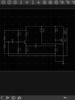
Why did the so-called "Tesla Coil" change from 1:200 turns ratio in your original post to a 1:1 turns ratio, as shown in IMG_0059.PNG in your post #6? How does the "ground" end of the secondary winding couple a feedback signal to cause oscillation in the circuit? What waveforms are expected and measured at the emitter of the NPN transistor driving the MOSFET gate? Why is the MOSFET biased into conduction most of the time? How much current does the MOSFET draw from the 60 VDC supply? Are you aware of the pulse-width and duty cycle limitations of the MOSFET?

Please re-draw the schematic to (1) include ALL components present in the actual AS BUILT circuit with (2) ALL components identified by nomenclature such as Q1, Q2... R1, R2... D1, D2... T1, T2... etc. and (3) ALL components identified by part number, value, and/or manufacturer's part number. For example: Q2, IRFP450A n-channel power MOSFET; or R3, 700 ohm, 10 watt non-inductive power resistor, Vishay part number ... ; etc.

It would also help us to help you if you provided a link to whatever Internet page you found your original drawing, which appears to be a "screen shot" of an unspecified schematic-capture program that you ran on your personal computer. Also, Tesla coils are invariably custom, hand-made designs, no two exactly alike. They are also high-Q, resonant, air-core transformers that always operate in a pulsed mode. They are difficult to model accurately in simulation programs. Knowing how your coil is constructed could help us to determine what is wrong with your "Tesla Coil Driver" circuit.

There are also "flyback transformer" circuits that, while resonant and using ferrite magnetic cores rather than air cores, are sometimes called Tesla coils. Hobbyists often start with these in their attempts to build and understand high-voltage circuits. If that is what you are trying to drive, perhaps a flyback transformer salvaged from an old television set, please let us know that.

It should be possible to drive almost anything in pulsed mode with the IRFP450A power MOSFET, but because transformers store energy in their inductive fields, protection from "spikes" that occur at fast-changing current edges is absolutely necessary. A few digital storage oscilloscope (DSO) images could help you discover where the problems are that lead to MOSFET failure.
 
Sorry my schematic editor is limited in what it can do. The design is subject to change. I missed the transformer ratio entry on my second attempt. I don't know the particulars of all the parts, they were from many different sources. I have a limited budget and don't have a digital oscilloscope. I suspect that feedback spikes are the problem. I was thinking of using 1n5388b zener diodes to short these spikes at around 400v. I will send a picture to give you some idea of what I am working with.
 
The primary is 4 turns 12 gauge copper wire close wound on a 6 inch diameter pvc pipe joint fitting. The secondary is 860 turns 22 gauge magnet wire on a 2.25 diameter pvc pipe. It is air core. All the designs are my own.
At 30v and with a 300 ohm resistor replacing the 700 ohm resistor it will arc to a screw driver an inch or better. At 60v and as shown it works for a couple seconds but after arcing to the screw driver the mosfet fails with a little crack sound.
I think the arcing is causing a feedback transient to exceed the ratings of the mosfet.
 
The diodes are cheap although bulky. My schematic editor won't let me post the entirety of the proposed circuit. I was hoping to get an educated opinion about if this will protect the mosfet sufficiently.
 

hevans1944

Hop - AC8NS
Well, it's been awhile since I last farkled with Tesla coils... I think I left those behind, shortly after the onset of puberty, in favor of more interesting pursuits... and that was waaay before metal-oxide-semiconductor field-effect transistors or MOSFETs were invented. You might be better served by visiting any of several Tesla forum websites. This one appears to be nice.

The only application I have had lately for power MOSFETs is as full-wave bridge drivers for PWM current control of largeish stepper motors, but most of the heavy lifting there is performed by motor-driver integrated circuits with application notes describing how to protect the external MOSFETs from so-called "inductive kickback" created by rapid switching of current in the motor windings. Not exactly rocket science, but similar protection schemes are presumably used with Tesla coil drivers.

Biggest problem with full-bridge drivers is shoot-through, which is a timing problem that occurs when the high-side and low-side MOSFETs, series-connected between the power supply rails, conduct simultaneously and unintentionally for a brief period of time. Depending on voltage and current levels involved, total destruction of one or more MOSFET devices can and does occur within a microsecond or so. The only cure I know of is careful timing and wave-shaping of the gate drive signals to ensure both MOSFETs are never driven on at the same time. A good IC high-side/low-side driver takes care of this for you. And sometimes the intrinsic body diode of the MOSFET will conduct to absorb voltage spikes, but I would not rely on that.

A cursory Google search for Tesla coil MOSFET drivers turned over a lot of typically uninformed hobbyist crap. There does not appear to be any actual real design effort going on anymore, like it did thirty-something years ago, and shortly after power vacuum tubes (for awhile) began to replace rotating tungsten spark gaps as the primary interrupter. I personally still favor this mechanical approach because it is very robust. However, it appears to now be all "cut and try" or "plug and chug" experimental-only efforts... which is okay for hobbyist pursuits, but is a very slow way of learning anything.

You will notice that the circuit I linked to does not allow continuous oscillation, although it is self-excited in a manner similar to your circuit. Instead, it uses a 555-based "interrupter control" to allow bursts of oscillations. This is still not ideal, but it probably works "gud enuf" for a table-top Tesla coil.

Bottom line is this: I don't think I can help you protect your MOSFET. Someone else here in the forum may chime in with more or better advice, but I think you would be better off seeking help in a forum devoted to Tesla coils. Just be aware of some of the nut jobs that hang out there, lest you fall down their rabbit holes. High voltages naturally lead to thoughts about Farnsworth Fusers and zero-point energy harvesting, which many of us here consider woo-woo subjects unworthy of wasting our time. Your mileage (or kilometers) may vary.
 
There will be a diode in the fet so that the source/drain potential cannot be reversed. Thus the lower 10 zeners will do nothing.

The souce/drain voltage can be limited by putting a zener between drain and base so limiting the turn off speed when the drain gets too high.

If the oscillation stops, then the fet will be turned on hard and will not last long. If I were designing this, I would use a separate oscillator with the fet capacitor coupled and biased to be off normally, only turned on for a short time. It should be possible to set the on time to get the right current at a particular supply voltage.

I have never seen a good description of a Tesla spark generator. I assume that primary and secondary windings are tuned to the same frequency and there is critical leakage inductance to get maximum energy transfer. Someone must have done the analysis.
 
I see what your saying about the ten zener. Can the internal diode handle the inductive spike current? Will the zeners react fast enough to handle any voltage spikes above 400 volts? This is more or less a "snubber" circuit isn't it?
Are you talking about a class c amplifier?

Thanks to all the contributors.
 
No
You have gone back to kinky wires. Ground has three levels - why?
Turn off spikes put high voltage on the drain, not negative spikes.
The zeners should go to the gate to limit the turn off.
The diode you have added across the fet is in parallel with the internal diode and may reduce the fet dissipation if it acts as a zener..
There is a mess around Q1.
Look up the specification of the fet and see what energy it can stand when overvoltaged.

I suggest you get a schematic from a working device.
 
Top