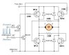
Using an arduino uno and 4 transistors as shown in the schematic I would like to flip the current direction across a coil of wire depicted by the solenoid here. The current also has to be fairly strong (a few amps). The transistors are all TIP3055's. http://www.onsemi.com/pub_link/Collateral/TIP3055-D.PDF
The circuit seems to do perform ok up to about one amp. Above about 1.3 amps something changes and i'm not sure about what it is. The current seems to prefer one path to the other. I took some measurements while keeping the DC supply settings constant. Here is what I found: whenever the current flips the current changes between 1.3 and 1.5 amps. At 1.3 amps the supply also measures a much higher voltage.
When Q1 and Q2 are "on" (current passes through them) and Q3 and Q4 are off, 1.5 amps is measured. When Q3 and Q4 are on and Q1 and Q2 are off, 1.3 amps are measured. When I try to increase the current using the supply Q1 and Q2 allow more current through but Q3 and Q4 still only allow 1.3 amps.
I measured the collector-emitter voltages of each transistor as the circuit was running and here is what I found:
On Off
Q1 .94 1.61
Q2 .42 2.08
Q3 .69 2.25
Q4 1.18 1.59
I've made sure that each pin on the arduino is supplying the same voltage and I don't think there any inductance effects going on. And the base-emitter/ base-collector voltages remain the same as well. Could this be due to faulty wires or a bad breadboard? Or is there an obvious problem with the circuit?