Maker Pro
Maker Pro

Simple SW receiver on 3V?

I agree with you aurelZ. You are absolutely right. Building is a lot of the fun of it, but I think some here want to know more so that they can get involved and offer as much help as possible. I think the main bit of advice is don't restrict your self to 3V. 9 volts gives you so much more choice when looking for circuits.

As for old designs vs new ones, that has to be another string surely. Again, I think you have a point. Modern designs using chips and digital processing hide half of what is going on and for the experimenter and learner, have less to offer than so called "old" designs.
 
Look i don't have nothing against using 9V battery which is good for so many other
purposes but not for a radio /audio circuits simply because battery life is short
and that battery can be used with small current devices only.
 
Do you want to listen on headphones or on a speaker?
Restricting the battery voltage to 3V when the battery is new or is 2V when the battery needs to be replaced reduces the maximum loudness. To reduce battery current all the time even when not playing, a class-AB amplifier should be used, not a current-hungry class-A single transistor.

I designed a simple class-AB amplifier and a simulation shows some distortion all the time and a maximum output power of only 0.015W which is very faint. If a 9V battery is used then the power will be 0.5W which is 33 times more.

If you used a modern PAM8403 bridged class-D stereo amplifier IC then its output will be 0.8W per channel at low distortion when the battery is 3V and will be 0.5W per channel at low distortion when the battery has dropped to 2.5V.
 

Attachments

  • simple audio amplifier.png
    simple audio amplifier.png
    48.5 KB · Views: 9
Look i don't have nothing against using 9V battery which is good for so many other
purposes but not for a radio /audio circuits simply because battery life is short
and that battery can be used with small current devices only.

Well, you asked for advice and one piece of advice was an alkaline PP3 would give you plenty of life with a small radio. It may not have been the advice you wanted but there it is.

Also don't forget this is a forum and a lot of people will come across your question (which is a good question because it has generated lots of discussion) and learn from it. The answers people give are intended by them for anybody who cares to read them and not just you.
 
Sure, use a little 9V battery with a simple class-A audio power amplifier made with only one transistor.
With a 3V supply and an 8 ohm speaker then for low distortion the speaker must have 1.5V across it and the speaker must have the remaining 1.5V across it. The resistor also must be 8 ohms then the current all the time is 1.5V/8 ohms= 188mA. An Energizer 9V alkaline PP3 battery will last for 1 hour when its voltage drops to only 4.8V.
 
Ok all 5!
But i don't hve in plan to buy anything
i have a lot old junkbox parts from CRT TV and monitors and that is just for hobby..
Your AB class amp is not bad and i recently build one very similar to yours
yes it has low output and can be used with phones .
Also i have few amp chips which can work on 3V giving cca 100 to 150mW or maybe less
i don't know exactly
In this concrete circuit i think that author use 2k phones,so they are with high impedance
probably 1+1k in serial connction.
 

hevans1944

Hop - AC8NS
Hi folks!
I was looking into circuit of Shortwave receiver which
work stable and solid on 3 V...mean 2x1.5V battery.
I saw many circuits on net and on youtube but most
of them use 9V battery ,which from my point have small time
of duration.
thanks in advance!
I have owned this little Panasonic "pocket sized" AM-FM-FM Stereo superheterodyne receiver, as shown in the image below, for many years. It uses two AAA 1.5 V alkaline cells. Volume from the built-in loudspeaker is not very loud, but I would normally use it with a stereo headset. These radios are still available for sale, used, on eBay but caveat emptor before laying out big bux. It is a Panasonic model RF-455. I did not find any other radios this small that operated from 3 V, much less have shortwave bands, but there are plenty larger receivers available that feature "full coverage," whatever that hype means... as I am sure you are aware.

It could be that everyone shifted to 9V batteries because it was easier to design silicon transistor radios with that voltage available. I haven't looked inside my radio for twenty years or more, but will do so soon because the volume control potentiometer needs to be cleaned and lubricated. I would almost be willing to bet that Panasonic used germanium transistors in this radio. I know the parts are really crammed together inside, axial lead components inserted with one lead directly into the circuit board and the other bent over into a "U" shape and inserted into the circuit board. It really blew my mind (as a kid) when I first saw this construction technique. I had somehow thought there was some sort of rule that components had to lay flat on circuit boards!

Unfortunately I have not been able to locate a schematic for this fine receiver yet. I am sure it could be easily adapted to receive short-wave bands from 1800 kHz up to 30 MHz because it already receives AM broadcast (530 kHz to 1600 kHz) and FM broadcast (88 MHz to 108 MHz). Someone just needs to change the local oscillator frequency and maybe soup up the front end a little.:D

Ugh! Not so fast. The transistors this radio uses are probably long obsolete and out of production. I wonder if a superhet radio could be designed from a CMOS version of the 555? That little puppy will never go out of production or become obsolete! And being CMOS, it would probably run fine off of three volts and draw almost no current. Or maybe someone smarter than me could design a CMOS radio on a chip (if that hasn't already been done) that I could buy for fifty cent on eBay... It would tune from DC to Light, or some reasonable subset of that.

il_570xN.1805950636_odno.jpg
 
Last edited:

hevans1944

Hop - AC8NS
Here is a link to a simple one-transistor short-wave superheterodyne receiver (shown below). Looks like it may work from two A-size dry cells. All you old timers out there, pining for a comeback of the All American Five Tube Superhet Radio, can be welcomed into the transistor world with this one.

Superheterodyne receiver with one transistor
This simplest ever circuit of the reflex superheterodyne radio receiver includes only two semiconductor components - a transistor and a diode. It can receive signals of MW or LW band. The intermediate frequency (IF) is 455 KHz.

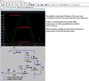
The circuit (see Fig. 1.) uses standard components - the loopstick antenna (L1, L3), the heterodyne RF transformer (L2, L4) and the IF transformer (L5, L6) are from an AM radio. The receiver has very good selectivity, but the sensitivity is the same as for a good one-transistor receiver.

superheterodyne_receiver_with_one_transistor.gif


Fig. 1. Circuit diagram of the superheterodyne reflex receiver

T1 - 2N168A, D1 - 1N34 (germanium);
L1, L3 - a loopstick antenna from an AM radio;
L2, L4 - a heterodyne RF transformer;
L5, L6, C8 - a resonant RF transformer;
R1 - 250 Ω; R2 - a potentiometer of 5K; R3 - 270K;
C5, C8 - 10 nF; C6 - 0.05 μF; C7 - 10 μF x 6 V;
Headphones with high impedance;
Power supply - 3..4.5 V.

How this superheterodyne reflex receiver works. The loopstick antenna (L1, L3) receives the signal of a frequency that depends on the resonant tank L1C1C3. From the coupling coil L3 the signal goes to the base of the transistor T1. The transistor works as a heterodyne and as a mixer in the same time. The heterodyne frequency is determined by the resonant tank L2C2C4. If the resonant tank L1C1C3 of the loopstick antenna is tuned to 1 MHz, and the heterodyne is tuned to 1.455 MHz, the mix of this signals will produce IF frequency of 455 kHz (1.455 - 1.0 = 0.455 MHz), and the image frequency of 2.455 MHz (1.455 + 1.0 = 2.455 MHz). The last one will be rejected by the IF resonant tank L5C8.

The IF signal of 455 kHz goes through the coupling coil L6 to the diode D1. The diode detects the IF signal, and the audio signal develops across the potentiometer R2 (the volume control). The capacitor C8 blocks RF pulsations. By the way, this capacitor connects coils L3, L4 to the ground for AC current.

From the capacitor C8 the audio signal goes to the base of transistor T1. Coils L3, L4, L5 have very small impedance for audio frequencies, so do not affect the audio signal. From the collector of T1 the audio signal goes through coils L5, L2 to the headphones. To prevent any unnecessary RF feedback, the headphones are blocked by the capacitor C5. The same capacitor also provides connection for AC in the resonant tank L4C2C4.

The circuit diagram of this superheterodyne reflex radio was published in the magazine «Radio-Electronics» in December of 1960 year.
 
Well this time i like "WallOfText"
Most of things you said i already know but is not bad to read complete explanation
and i read it.
Hmm i am interested for this small Panasonic am7fm radio, it is nice
and to let you know all transistors inside are NPN not PNP and not germanium than are silicon
made in Japan, in those times Japan made best fm radios in the world.
Most of copies comes also from HongKong or Taiwan at those times.
there are really lot of big electronic companies from Japan
NEC
Toshiba
Mitsumi
Sansui
Tensai
JVC
Panasonic
Saniyo
Hitachi
etc..etc..

I have schemetic of one am/fm radio on 3V batt
And i currently working on one FM only with Varicap tuning
Maybe i can post schematic if someone is intersted.
Currently i have stupid problems with local oscillator/mixer
yeah i tend to use one transistor for two jobs and in general that work
BUT most Hifi tuners use 3 transistor
if first version don't give good results then i will switch to 3 tr version.
I will post it when i fix all problems.
So far IF 10.7 amplifer work execellent , FM Weiss demodulator work but need
more modification and 2 tr front and makes me nervous.
Maybe i will use better transistor or increase voltage and use power supply
with which i can better adjust varicap diodes.
for now i use BB910 which work with good on 3V but must be at leat two of them
to operate one side for osc/mixer and one for main tuning part after RF presmplifer.
ok !
 

hevans1944

Hop - AC8NS
I envy your experience with RF circuits! When I was growing up and beginning my journey down the road to learning electronics, radio frequency circuits were both fascinating and fairly easy to "play" with using vacuum tubes. Of course I didn't understand the math and had only a fuzzy idea of how IF amplifiers or FM discriminators and FM ratio detectors worked, although I thought I understood AM detectors. As a kid, I had virtually no test equipment except for what I could assemble on my own from junk radio and tv parts, mostly RF oscillators and signal tracers. Worst of all, I had no way to measure frequency except with an "old" Hallicrafters ST-38 AM short-wave radio that Dad had purchased after being liberated and returning to the States from a German POW camp in 1945, a year after I was born. By the time I was old enough to appreciate the receiver for what it was (a magical gateway into the world of short-wave radio listening), Dad had lost interest in it and I was free to use it... if I could figure out a way to afford to replace its vacuum tubes when the filaments eventually burned out, and somehow erect a long-wire antenna in the residential neighborhood we lived in. There were no HOA restrictions back then (late 1940s to mid 1950s), but the Air Force kept us moving around a lot so it was impossible to have any sort of "permanent" antenna.

I remember being especially fascinated with reflex receivers, where a common amplifier stage was used for both audio frequency as well as radio frequency amplification. I had no idea of the "superposition principle" or its requirement for linearity of the amplifier to avoid intermodulation between the audio spectrum and the RF spectrum. Didn't learn about that until I took electrical engineering college courses in the 1960s, but it didn't stop me from experimenting. I also was fascinated with regeneration and especially super-regeneration RF circuits, but those had already been pretty much replaced with super heterodyne circuits by the time I came along, except for a few die-hard hobbyist types who couldn't let go. Hmmm. I may try to revive my interest in such things at this late date, just to see what "improvements" might have been made, especially in the area of "self-quenching" that allowed the gain to be increased to just below the point of self-oscillation. A super regenerative superhet is a definite project possibility!

Glad someone finally gave me some positive feedback on my "WallOfWords" dissertations. Only a few electrons are mildly inconvenienced by those lengthy missives, and it allows me to exercise my declining cognitive skills. For those who dislike them, most modern keyboards have a key labeled "DEL" or "delete" that will automagically remove, in a single keystroke, whatever is bothering you. Lately I have been feeling like Hal, the AI-gone-mad computer in the movie "2001: A Space Odyssey" as its memory modules are sloooly being remoooved by the Dave Bowman character (Keir Dullea). I think something is turning off my brain cells. A recent head x-ray showing something wrong in my hippocampus seems to confirm such a diagnosis.

I can appreciate the desire to minimize power consumption in portable radios. I once purchased (at exorbitant prices!) nine or ten unmounted silicon solar cells from Radio Shack with the intent of using them to power an HP-67 calculator I had recently purchased to replace the HP-35 that I thought I had "outgrown." Turned out the HP-67, with its magnetic card-strip reader/writer was a power hog and there was no way I could carry around (much less afford) a solar cell array large enough to operate it. I still need (to this day) to mount the Radio Shack cells in protective enclosures that do not appreciably attenuate the light spectrum, so they do not continue collecting dust instead of sunlight in my junque box, full of now mostly obsolete parts.

I will close this post with a link to another forum I found rather fascinating, The Radio Board, which welcomes both beginners as well as experts.
 
by the way
do you maybe know for some links to
FM tuner front ends schematic?
I am looking trough google but there is no good or concrete links
most of that are pure trash
 

hevans1944

Hop - AC8NS
by the way
do you maybe know for some links to
FM tuner front ends schematic?
I am looking trough google but there is no good or concrete links
most of that are pure trash
I don't know of any links for free schematics of FM tuner front ends, although IIRC some kit hi-fi receivers circa 1950s to 1960s were sold with pre-built FM tuners because DIY construction was so tricky. There may be schematics, probably for sale, not free, available for these front ends. If I can remember the manufacturer names I will look into it... Heathkit and Fisher come to mind, but there were probably dozens of others, at least until Japan took over the hi-fi market with lower cost, more features, and better quality. I haven't checked The Radio Board forum that I just recently joined yet.

Google search results are heavily influenced by a hidden agenda (besides money) known only to Google. Constructing better search strings sometimes helps, but not often IMHO. You can daisy-chain for days, following links that are useless as far as real information is concerned. I haven't found a solution to this problem, but the folks who developed my Firefox browser (mozilla.org) are looking into it.
 
Google search results are heavily influenced by a hidden agenda----

Yes you have a right..that is why I more and more use Bing search.
 
Top