"There is nothing wrong with the 4.7 uF capacitor. Leave it in the circuit as shown."
Here is your answer:
LOADING
The whole success of picking up a radio station is the RECEIVING CIRCUIT. The receiving circuit is the coil and the signal in the air (from the radio station) must go down the centre of the coil.
It cannot pass over the top or the bottom of the coil. Only the signal that goes down the centre of the coil is received.
As you can see, the centre of the coil is not very big and it is amazing that the signal can pass down the centre. But it does, and that is the only signal that will be amplified.
This signal is passed to the capacitor and we have explained how the signal is gradually increased and increased in amplitude until it is as large as 500mV. The signal from the radio station may be as small as a few millivolts, but as it keeps pushing the "swing" back and forth, the amplitude get larger and larger.
If you put your finger on the "swing" you will prevent it get larger and larger and it only requires the slightest touch of your finger to prevent the swing gaining full amplitude.
In electronic terms, your finger is called LOADING THE CIRCUIT and since we have to pass the signal to further stages of amplification, we need to "tap" or "load" or "pick-off" a signal.
The aim is to load the circuit as least as possible because the actual energy entering the circuit is very small.
In fact, this is all the energy we can remove as that is all the energy entering it.
Because a very small amount of energy is entering the "front-end" we classify it having a very high impedance. It is very difficult to provide a value of impedance for this circuit because impedance has the term "Z" and the circuit is operating a very high frequency so resistance values are not the same as impedance values.
The actual resistance of the circuit is ONE OHM but the impedance is more like 10,000 ohms to 100,000 ohms.
We can explain its high impedance if we put a 100,000 ohm resistor across the circuit. The waveform will be reduced very slightly. If we put a 10,000 ohm resistor across the circuit, the signal will be reduced a reasonably large amount. If we put 1,000 ohms across the circuit it will stop working.
This means a load of 100,000 ohms will have the least effect.
In a crystal set, the diode creates NO LOAD until a voltage of 350mV is reached. It then passes excess voltage to a crystal earpiece that has a very high impedance. That's why a crystal set will produce a good output. The LOADING is very small.
When a transistor is connected to the TUNED CIRCUIT, it starts to put a load on the circuit after 600mV and this load is VERY HIGH. The "resistance" of the base-emitter junction is about 1k and the signal will find it very difficult to rise above 600mV because the incoming energy is not sufficient to increase the voltage.
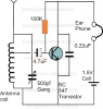
Adding a capacitor between the base and the front end allows the transistor to be self-biased and get a turn-on voltage of about 600mV from a base-bias resistor.
The FRONT END is now separated from the transistor and ANY voltage it is producing will be passed to the transistor via the capacitor.
Whereas, with the crystal set, the first 350mV could be produced without any loading, the circuit is now loaded AT ALL TIMES.
This means we have to load the circuit as lightly as possible to be able to pick up individual stations.
The only way we can do this is to use a capacitor of the smallest practical value and this has to be worked out by trying different values. If the value is too small, the transistor will not detect a small signal. If the value is too large, the circuit will stop working.
Values such as 1n, 10n and 100n are suitable.
Values such as 1u, or 10u will be too large.
The CRYSTAL SET loading and a transistor load are completely different.
The transistor loads the front end ALL THE TIME and that's why you need to use a transformer or other ways to reduce the loading. Sometimes a Field Effect Transistor is used as it puts almost no load on the front end.