Maker Pro
Maker Pro

Serial communication problem.

hevans1944

Hop - AC8NS
They all had there very good and lasting use!
Yep, but with emphasis today on had. There are so many ways to implement serial comm links today, including the ubiquitous USB, that personal computer makers no longer provide either DB-9 or DB-25 serial ports. And of course the so-called Centronix DB-25 "parallel printer port" (which I actually found useful as a general-purpose 8-bit I/O port) was long gone even before the demise of the serial comm ports.

So what's a person to do when confronted with legacy RS-232 data links? Earn while you learn is my motto for that. Or, in my case, earn while I refresh my memory on that.
 
Hop,
No doubt about it, the RS232 is an obsolete thing.
I have used it in so many ways,practically have used most of the functionality of the DB25 pins...
that was in the mid 80's to mid 90's.

Nowadays, the way to go is with USB.
Except cases like this one here:
HellasTechn has to meet the defacto exiting equipment mode of operation.

BTW,
Referring to RS232 as "protocol" is wrong, it is merely an interface standard("physical layer"- electrical and mechanical standard) not a protocol !!!
 
The Max232 and Max3232 are not the same!
Which one are you using?
I actually have both MAX232 and MAX3232EPE chips. The one i use is a MAX3232EPE...

As far as i remember the only difference they have is that the max3232epe do not have internal 400K pullup resistors on TTL inputs.

Hmmm i will try to switch the 3232 with a 232 chip to see what happens. I doubt there will be any difference though, then i will give it a shot with 1uf capacitors instead of 10uf
 
Some differences are:

1. MAX3232 doesn't have internal pull-ups on transmitters TTL inputs(like you mentioned),
thus it's unused inputs have to be tied to VCC or GND.
while MAX232 is internally terminated and can be left open.

2. MAX3232 has ESD protection while MAX232 doesn't have it (which may explain the burnt MAX232 IC's cases).

3. MAX3232 transmitters may operate at much faster rates than MAX232 (due to higher slew rate of the driver).

4. MAX3232 has larger supply range 3-5.5V while MAX232 is 4.5-5.5V

If you can use the Oscilloscope to measure the lines(with and without VCC to the MAX IC,it will reveal what goes on.

What is the length of wires you are using between the equipment?
How exactly is the GND wire connected?
 
Last edited:
The lenght if the lines would not exceed 5-6 inches.
the GND is as shown in the pic below.

Scopings are on the way !
 

Attachments

  • max chip.png
    max chip.png
    21.3 KB · Views: 111
Last edited:
Here are the scope images.
1. The RS232 source without anything connected on it.
2.The RS232 source connected on the max chip with power on.
3.The RS232 line connected on the input of the powered on max chip but with RS232 source disconnected.
4. The RS232 source connected on the of the powered off max chip.

Picture 3 shows that the max chip is introduceing 5Vdc on my rs232 line... I have tested several MAX232EPE and MAX3232EPE chips and some gave me the same while other did not.

The chips that would not give me ta DC voltage would work correctly both with and without power.

I have noticed though in all cases (with all max chips) that when on the pcb they would distort the signal on my RS232 line a little bit. I wonder if that is due to the capacitors value.

My conclusion is that all theese chips are probably counterfeits that will some time eventually fail.
 

Attachments

  • 1.RS232 SOURCE.PNG
    1.RS232 SOURCE.PNG
    8.6 KB · Views: 99
  • 2.SOURCE ON MAX.PNG
    2.SOURCE ON MAX.PNG
    11 KB · Views: 103
  • 3.MAX W.O. SOURCE.PNG
    3.MAX W.O. SOURCE.PNG
    7 KB · Views: 84
  • 4.SOURCE ON MAX W.O. POWER.PNG
    4.SOURCE ON MAX W.O. POWER.PNG
    9.2 KB · Views: 102
Looks like you have found the problem,it is the +4V DC shift that the MAX chip (probably,make sure there is nothing else causing that)introduces on the RX lines.
That voltage shouldn't be present.
This shifts the signal level to faulty value of about 0V (fig 4)

Have you tried same scoping with the MAX232 ICs?
Were the MAX2323 ICs bought from a reliable representative of Maxim,or on Ebay?

Scoping should preferably be dome on the Rx lines-pins of the IC.
 
Interesting.
I add problems with cheap stuff bought from Ebay/china as well.
Learned my lesson,the hard way , and avoid buying ICs from china any more. :(
 
There is a cheaper solution in your case.
What you actually need is "2 receiver only",you don't need Transmitters at all.
That means you don't need the DC-DC +/- converter , thus no caps.

You can use the MC1489A IC (vcc=5v) that costs 0.7$(1PCS) on Digikey and Mouser.
It is an old 80's reliable IC, I used it a lot at the time...

In fact,
A receiver can be reduced to the simplest single transistor "level shiftier" it will cost you pennies...
 
Like this one. Only the Rx part is requred.

I wouldn't use that circuit as it is.

First thing is to protect the B-E junction of the Transistor from large negative voltage at "Mark" (Up to -25V theoretically) using a reverse diode.

Second thing is to eliminate the "transmitter part".

BTW,
the transistor can be 2N2222,2N3904 etc.

Here is the modified circuit:


Modified SimpleRS232.JPG
 
Last edited:
I will breadboard the circuit and let you know.
Boy i have such a tiny knowledge on electronics that i dont even understand how the transistor works. I am not able to understand the circuit alone.

i wonder how i could change that ? for example i have read about transistors that explain how they are made but not how biasing affects their operation...

Here is a very simplified explanation:

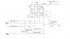
In the schematic above the transistor is used as a "switch" which has 2 states "on" and "off".
The functionality is of a logic inverter.
Unlike a "pure logic device" ,it has different input and output voltage levels i.e it performs voltage shifting/translation.

In the "on" state of the Tr. ,the "switch" is closed and the output is 0-volts.
For that to happen the Tr. should be "foreword biased" into conduction(actually saturation).
That needs VBE to be higher than 0.5V(actually about 0.8V,with the help of the presence of the base resistors),
it will happen when the input is in the "space" level( >+3v).

In the "off" state of the Tr. ,the "switch" is open and the output is at VCC volts.
For that to happen the Tr. should be "reversed biased" into non-conduction.
That needs VBE to be lower than 0.5V(actually -0.7V due to the protective diode),
it will happen when the input is in the "mark" level( <-3v).

Note :
If the input is open the condition of the Tr. is "off" !
(Self check:Can you explain why?)

That is basically the operation of an NPN bipolar transistor in a "digital circuit" functioning as a switch.

There are other applications where the Tr is used as Amplifier etc. in "analog circuits",
they are much more complicated to explain.
There is a lot of material about it on the WEB,and in EP as well .


inverter.JPG
 
Note :
If the input is open the condition of the Tr. is "off" !
(Self check:Can you explain why?)

Because BE junction is reverse biased.
What i dont get now is this : ttl signal is idle 0V and high 5V
the rs232 signal is >-3V (idle state), with the ec open the output will read 5volts and when rs323 pulses high >+3V then ec is closed affectively grounding vcc through the resistor so the output reads 0V.
Is it not oposite than what we need for TTL ?

We have a very basic ressource on this topic.

A more detailed explanation is in this pdf.

Thank you, i will read them.
 
Top