Maker Pro
Maker Pro

RF module not working at all. What am I doing wrong?

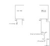
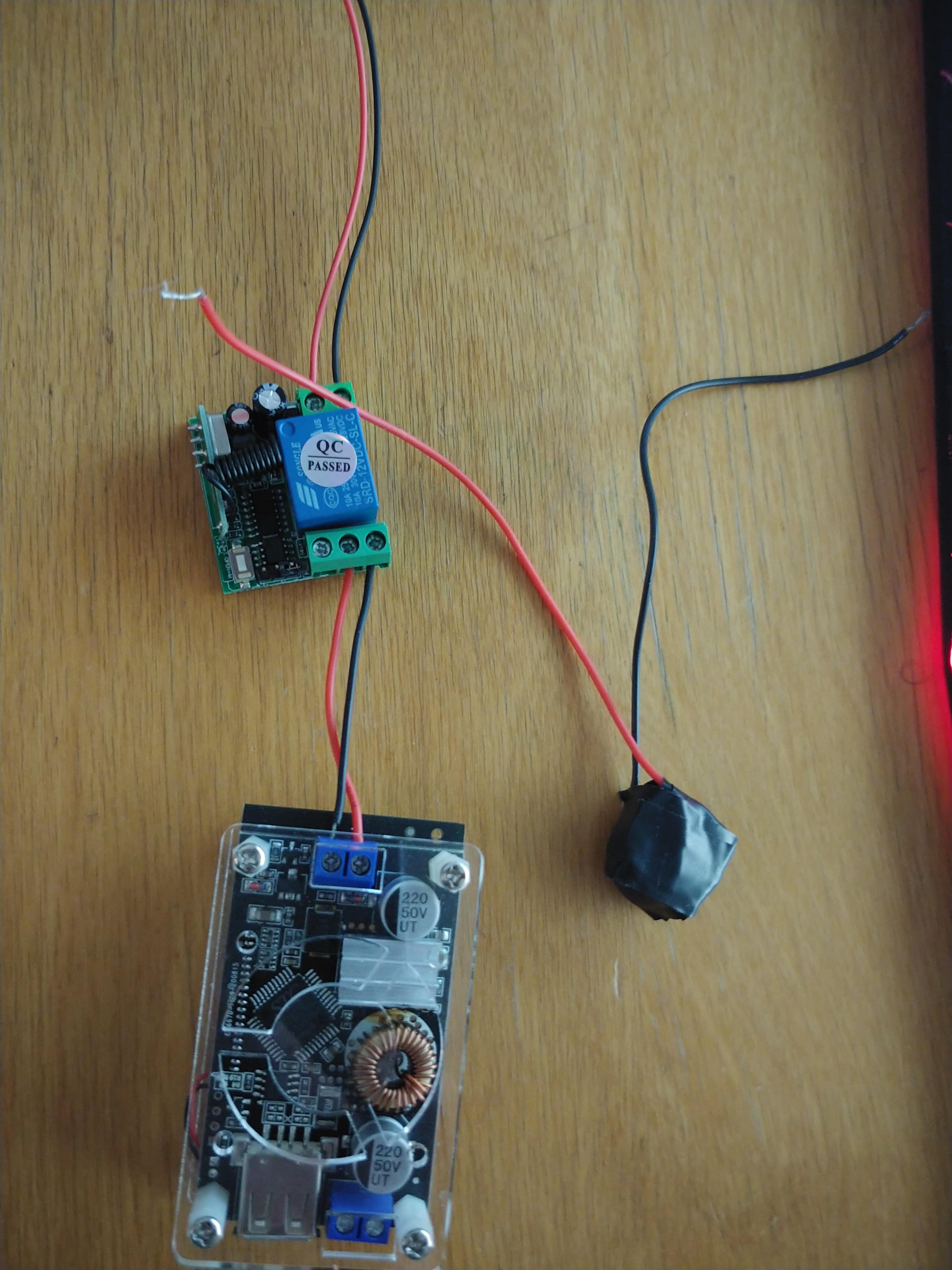
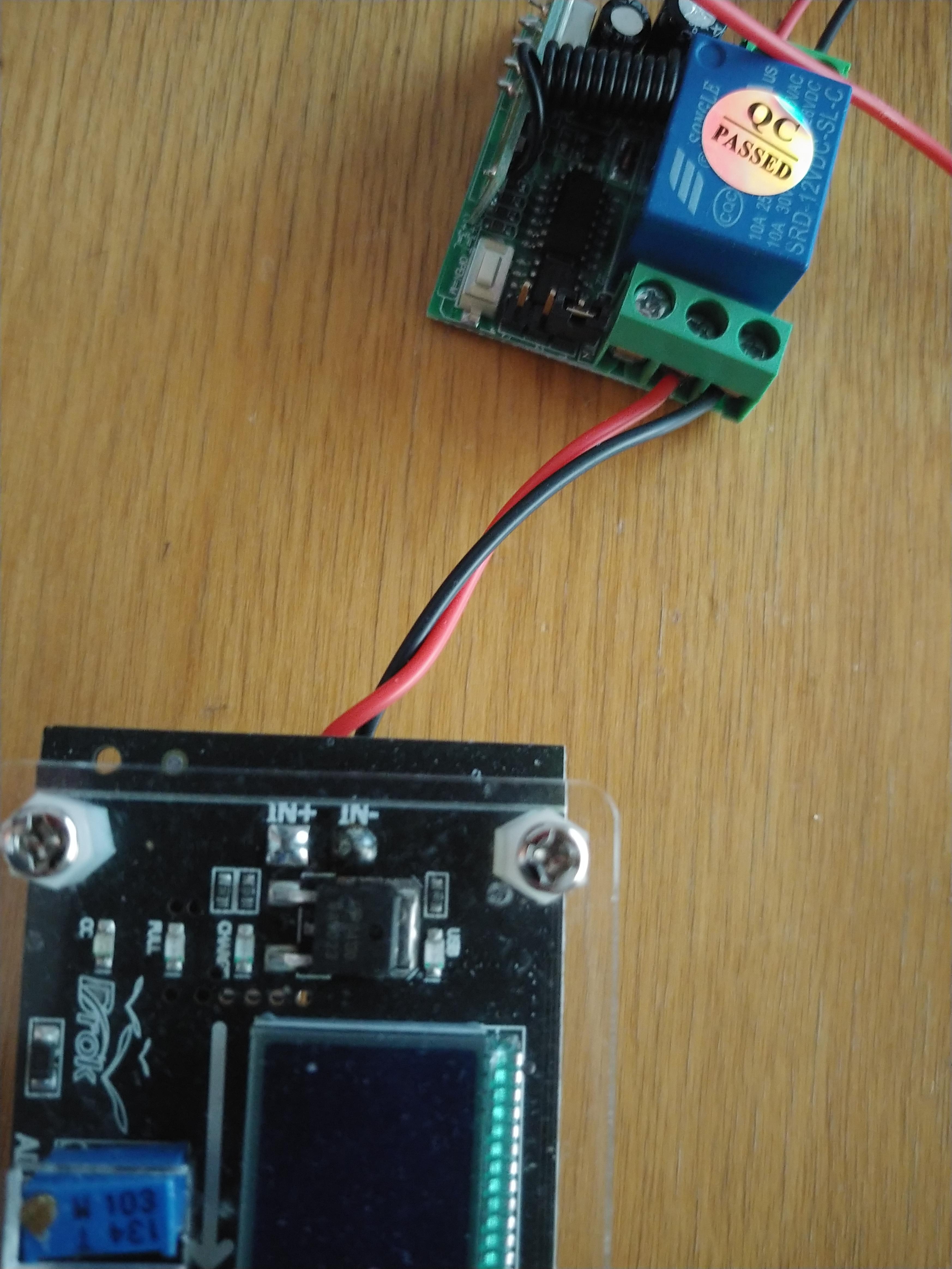
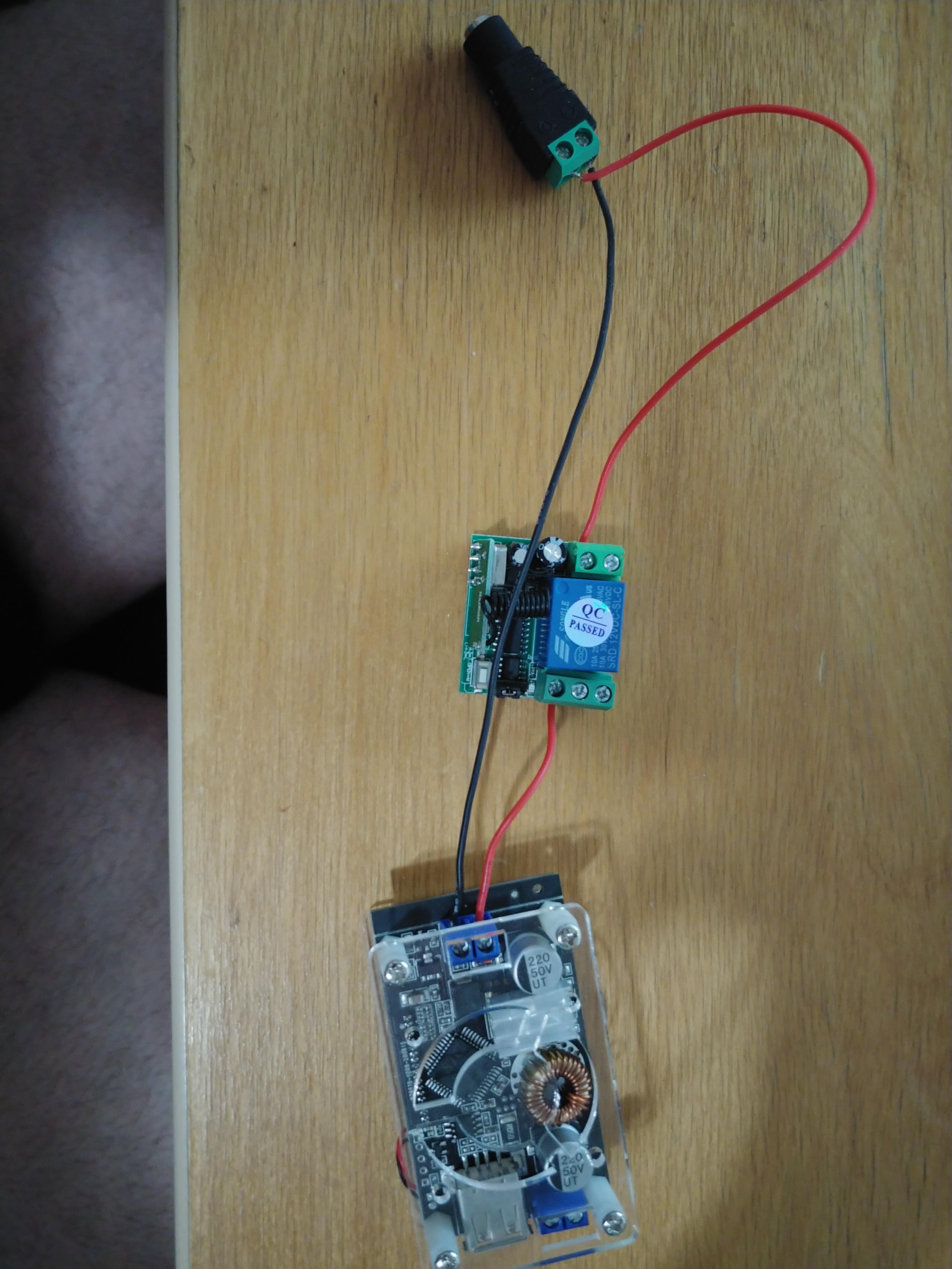
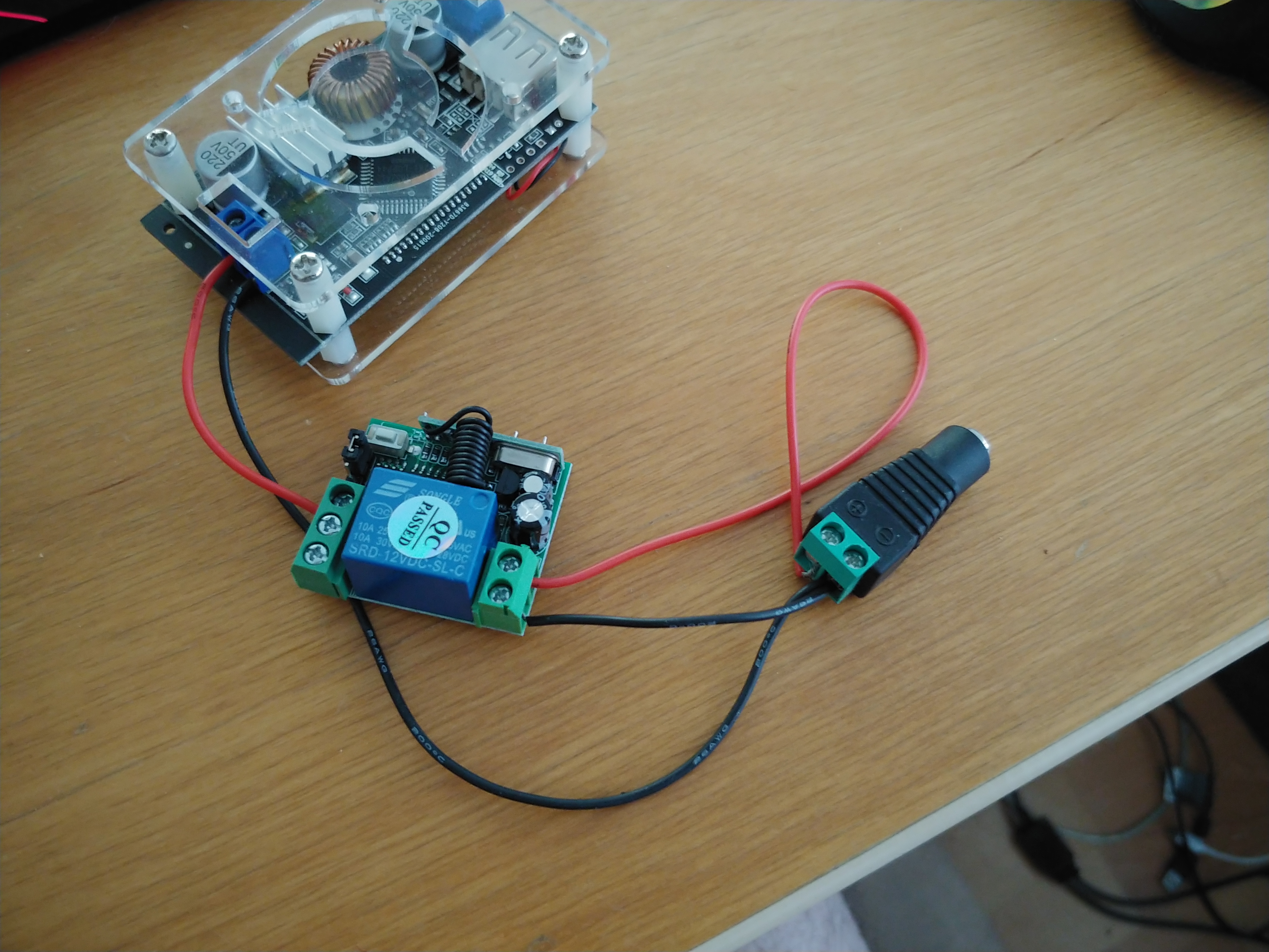
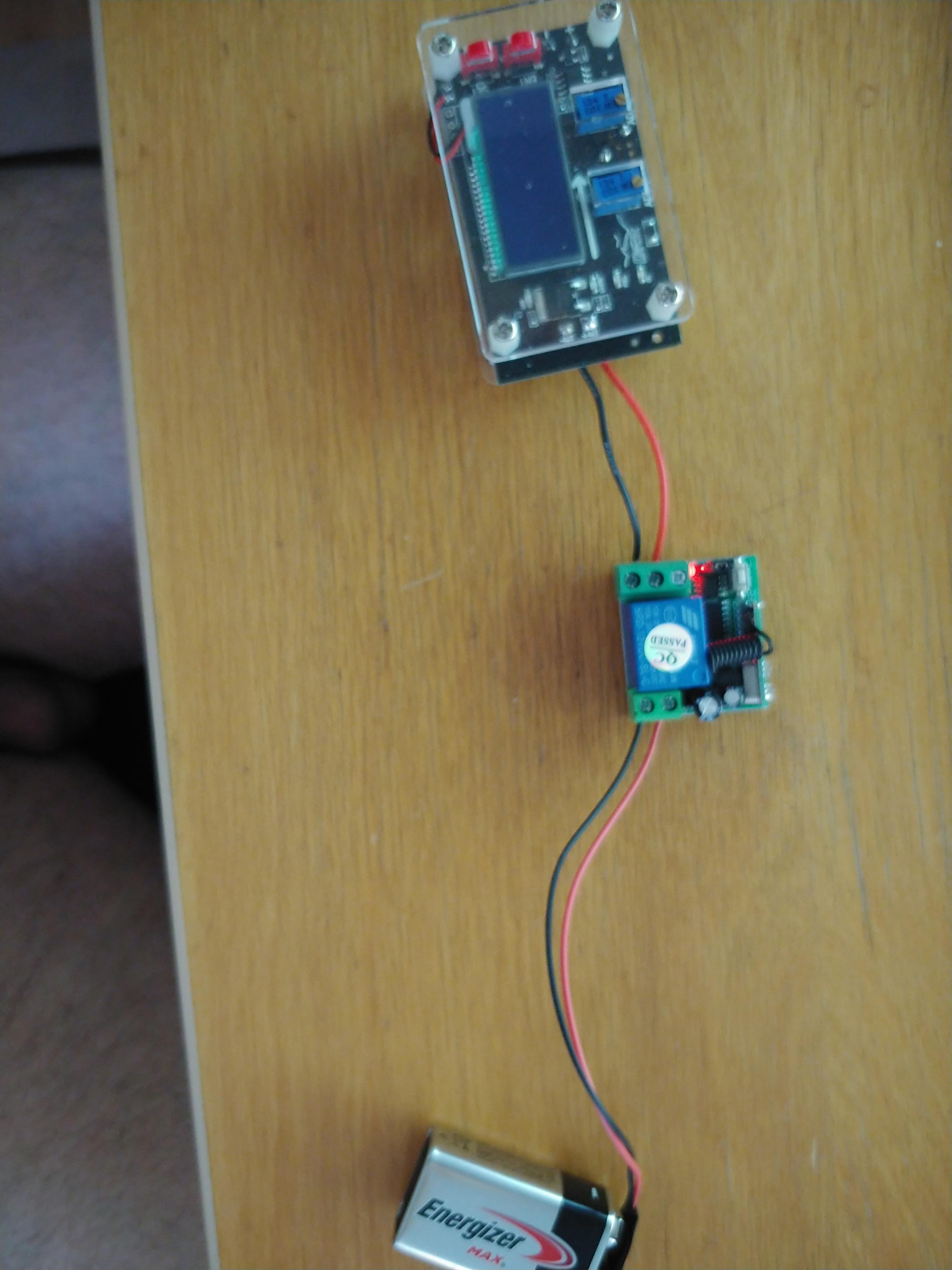
I got this in the mail from Ali Express, and I tried to test it by making a buzzer go off when I click the button. But no matter what I do, it doesn't seem to be working at all. It lights up when I connect power to it and I hear an audible click when I press the buttons on the controller, but it does not do anything. I switched the jumper around from the momentary switch to the toggle position and it did not do anything. I tried to put the positive and negative wires from all the positions (NO, Common, NC) and I have no result. I also tried both a 9v battery (fresh energizer max) and a 12v power supply.

Anyone have any experience with this particular RF module? I noticed most of them are identical except for the location of the terminals.


I have a picture below of my latest attempt and here is also a link to the product: https://bit.ly/3tcr3uB


Ea6sXVw.jpg
 
To begin with the specs say 12v operation so forget the smoke alarm battery and connect to some decent supply.
A 1A 12v DC power adaptor should suffice.

The output with these is normally a set of relay contacts commonly known as voltage free.
By the look of your output you have nothing supplying the contacts to give power to whatever the test unit is.

This in the instruction would be deceiving I must say, but then this is Chinglish......
Output voltage: DC

It sounds like the Tx and Rx are bound together as you say the relay clicks.
Never-the-less instructions are below in your link if needed.

What voltage does your "tester" unit run on?
 
Last edited:
To begin with the specs say 12v operation so forget the smoke alarm battery and connect to some decent supply.
A 1A 12v DC power adaptor should suffice.

The output is a set of relay contacts commonly known as voltage free.
By the look of your output you have nothing supplying the contacts to give power to whatever the test unit is.

This in the instruction would be deceiving I must say, but then this is Chinglish......
Output voltage: DC

It sounds like the Tx and Rx are bound together as you say the relay clicks.
Never-the-less instructions are below in your link if needed.

What voltage does your "tester" unit run on?

So this cannot be powered by a battery? I saw someone on youtube with the same thing and it did work with a 9V. I could make a battery pack with 4 CR2032 that would get 12 volts (I don't know about amps) but the thing is, even when I hook it up to a 12v power adapter (12v, 5 amp) it does absolutely nothing. It powers up but I still cannot switch anything on. I tried both the DROK and the buzzer (the buzzer has a minimum of 3V to a max of 24V).

I've seen this video (same unit) where the guy does some action going at first with a 9V before moving on to a lightbulb (which he has an alternative power source).

I read the instructions, but they didn't help. It isn't the power, and it isn't the wiring configuration. At this point I think I might have a dud device.
 
No, you have to get this idea of these little batteries powering devices with a specified current demand.
Battery power is fine as long as you go up in capacity, say (for example) 8 * AA NiMh batteries in series or a decent 3 cell LiPo.

It isn't the power, and it isn't the wiring configuration.

I beg to differ.
To repeat, see if it will sink in this time, the output is commonly a set of voltage free contacts.
What is the unit you have above the relay and what normally connects to the Red and Black wire leading to it..?
 
The device I have connected is a DROK DC-DC adjustable buck voltage converter. You can see it here https://amzn.to/3mveKGR

The wires are connected to the input of the DROK, the positive goes into the common, while I put the negative into the NC switch.

I have a fairly basic understanding of electronics and no real knowledge of RF. So if I understand you, it does not transmit any power when it is toggled, but the power needs to come from another source and the switch basically functions to complete the circuit?

I hate feeling like a dumbass.
 
Ok...... you can supply both from the one 12v battery.

First look at the photo number 5 at the bottom in your link which shows an underside view of the wireless board.

You will see a pcb trace coming from the common terminal of the relay on the right side all the way over to the left side of the board towards the + of your wireless supply terminal.

BUT, it doesn't come all the way, it stops short BUT you can put a drop of solder to bridge the gap.

This will allow your wireless power positive to now connect to the DROK through the COM and N/O relay.

I'll sketch up a circuit so you can follow.

The battery negative connects directly to the DROK black wire and the wireless input power negative.

Take note that in positive logic, i.e. relay energised, you should connect your load (drok positive wire) to the N/O terminal (normally open).
 

Attachments

  • UNTITLED.jpg
    UNTITLED.jpg
    20 KB · Views: 6
Last edited:
Wow really? It's that simple I did notice the solder bit and how it stopped short, that's why I knew you put the positive wire there. But I did not know you could just add another dab of solder to complete the circuit. I made a 12v battery by sticking four CR 2025s (I wanted to use 2032, but I didn't have enough on hand). I know the amperage will be low, but it did get both the buzzer and the DROK going, so that's good.

I'll wait for your circuit sketch, I'm also new to those, not what the symbols mean, but how the sketch translates to a real circuit board. It's an exciting new language.
 
Is this what you want? The small blob is the 4 CR2025s that I made. They work.

negative goes in to the NC part, positive goes into common.

H3ERsuB.jpg


ISdwIP5.jpg
 
Ok...... you can supply both from the one 12v battery.

First look at the photo number 5 at the bottom in your link which shows an underside view of the wireless board.

You will see a pcb trace coming from the common terminal of the relay on the right side all the way over to the left side of the board towards the + of your wireless supply terminal.

BUT, it doesn't come all the way, it stops short BUT you can put a drop of solder to bridge the gap.

This will allow your wireless power positive to now connect to the DROK through the COM and N/O relay.

I'll sketch up a circuit so you can follow.

The battery negative connects directly to the DROK black wire and the wireless input power negative.

Take note that in positive logic, i.e. relay energised, you should connect your load (drok positive wire) to the N/O terminal (normally open).

Ok it sounds simple enough. Positive from drok or other device goes into NO, positive from battery goes into positive terminal of relay, and negative of battery goes into the DROK. This must be done after the solder connection is complete.

Please correct me if I am wrong. I'll pull out the soldering iron tomorrow and add the dab of solder and see how it goes.
 
Simply show me what you connect to where BEFORE powering up.
And for the sake of Nelly, get rid of those b*** button cells and use a decent supply.
 
Simply show me what you connect to where BEFORE powering up.
And for the sake of Nelly, get rid of those b*** button cells and use a decent supply.

OK I'll use my 12v laptop power supply. I'll still use the coin buttons to test (gotta use them for something!) but I'll shop around for a 3 cell LiPo battery. I never used one, is the one in the link below what you're referring to?

https://bit.ly/39Su8rI
 
Ok so I couldn't sleep, I figured I'd use this time to solder the module and wire it up. I have the pictures here (BTW, I know, I REALLY need to work on my soldering skills).

The terminal I used will go into my 12v laptop powersupply if you think this is an OK job. BTW, I switched the jumper from toggle to momentary.

fkkgpBY.jpg


LlMoXux.jpg
 
Solder bridge, well , mmmm...might hold.

You also need a negative wire from your DC power jack inline socket (black) to your wireless unit negative terminal.

Before you switch on, just temporarily remove the Red cable from the jack socket, and..........
.................If you have a multimeter, I'd be inclined to test the polarity and the voltage level of that jack socket when it is plugged into your laptop supply.

Reason being most laptop supplies are 18v and upwards and that will blow the guts out of your wireless unit which is 12v max.

LiPo was just an example for a battery supply.
If you do not have any already, forget it.
They need a charger to suit just LiPo's.

Other form of cells which can be made into a 12v battery are.......... dry carbon cells ( torch batteries )
Rechargeable NiCad's( probably AA) rechargable Nickle Metal (NiMh) AA, sealed 12v lead acid battery from a security system, on and on........

What do you intend to use this DROK for anyhow, that is the determining factor.
 
Is the wiring below correct?

I'm using a DROK just to test it. What I want to do is make a light up toy based on the Rubber Ducky grenade from the Hitman (2016) (more info here: https://hitman.fandom.com/wiki/The_Pale_Duck). Basically I want to put a flashlight lightbulb or LED strip along with the power supply (This is why I need it to be battery powered, and by a small enough battery to fit in the rubber ducky) that would light up when I click the remote. Once this whole COVID-19 is under control (and with the vaccine being here it should be in the next 6 months) I hope that all the nerdy cons will reopen and I get to show off these toys to fellow congoers.

The DROK will also act as a multimeter to show how much voltage is going through it. My next test will be the buzzer. If that works I'll try to experiment with various batteries to see what I can do to make it work right and fit in the rubber ducky to make my toy work. I know those button batteries aren't optimal, but the are what I have for now. If they work I'll use them. I know they don't contain enough power to last for long.

rZLxAWV.jpg
 
HOLY SHIT IT WORKS! :D :D :D

I am soooo glad. Yes, it worked and lit up the DROK and the buzzer. That means it should work for my toy project and anything else I need an RF module for. I will order another one and try to make it work with a seperate battery for teh device. I have an idea of also making a bolt lock for added security in my home. I saw a video of someone doing it on youtube with a different RF module, but I'll see if I can craft it.

Thank you very much, I feel like I have advanced a small level in home electronics.
 
Good stuff.

If you need "small" then there really is no other battery than LiPo for good capacity.
Thing with them is, a small 3.7v single cell (say 500mAh capacity) would be about the same size as you wireless module.
When more voltage is needed, like 12v in your case,the cells are stacked together so the battery only becomes thicker.(3 cells 11.1v nominal)
You will find a small usb charger and LiPo's on Ebay, Banggood, Amazon etc.
 
Top