Maker Pro
Maker Pro

Remote Control Circuit with CD4017 - counter decoder

I see.

I just visited another electronic shop, a further one. Found CD4069UBE and CD4024BE :) but the bad news is they selling ONLY a normal 5V voltage regulator L7805CV (as the one you recommanded are not on demand in my country), I'm not sure whether it has LDO or what. So, can or cannot to use it? I've bought the c cells by the way.
 

KrisBlueNZ

Sadly passed away in 2015
That's good news!

You can use a 7805 or 78L05 but you'll need at least one more cell in the battery. 1.5V x 4 = 6V which leaves only 1V across the regulator. That's OK for a "low dropout" regulator, but it's not enough "dropout voltage" for a 78x05. 1.5V x 5 = 7.5V which leaves 2.5V dropout voltage across the 78x05 which is barely enough. 1.5V x 6 = 9V which leaves 4V across the regulator which is plenty, but a bit wasteful. The regulator will warm up while the relay is active but that is not a problem.
 
Haha. Understood. Great! Glad to hear that :D

Back to the Pierce Oscillator. I just re-check again with my dad (I'm studying at different state, far from my hometown), the ceramic resonator is CRB455E. I'm sorry that I said it was CRV455E. It's "B" not "V". And I found its datasheet. For me, I think should be ok.


And I got some questions here. I'm just wondering what if I replace the 455kHz ceramic resonator with 4.9152Mhz crystal resonator(very easy to get it over here), then set a 12 buffer output of ripple-carry binary counter 10000010 in binary (130 in decimal) so that 4.9152Mhz is divided by 130 and become 37.809kHz. Will it work? :)
 

Attachments

  • Datasheet CRB455E.pdf
    129.6 KB · Views: 161
I found this connection of the voltage regulator. So I need 10uF and 1uF capacitor right?
 

Attachments

  • 7805pinout.gif
    7805pinout.gif
    5.4 KB · Views: 1,251

KrisBlueNZ

Sadly passed away in 2015
That's not ideal because the LED is supposed to be driven at about 33% duty cycle. When you divide 455 kHz by 12, the Q4 output is low for 8 out of 12 cycles, then high for 4 out of 12 cycles. This is a duty cycle of 33% which is what you want. But if you divide 4.9152 MHz by 130, you will get roughly the right frequency on the Q8 output, so yes you're right about that, but it will have a duty cycle of 64/130 which is 49.2% not 33%. Also a few changes would be needed to the Pierce oscillator. So I recommend you stick with the ceramic resonator. The CRB455E looks good.
I found this connection of the voltage regulator. So I need 10uF and 1uF capacitor right?
Right.
 
Hey, I make this connection to my 7805 voltage regulator, do you think it is ok? :) Actually I got no idea on how much farad of capacitor, ceramic or electrolytic, is suitable for the voltage regulator? How the calculation goes?
 

Attachments

  • 2014-04-24 17.09.17.png
    2014-04-24 17.09.17.png
    202.6 KB · Views: 354

(*steve*)

¡sǝpodᴉʇuɐ ǝɥʇ ɹɐǝɥd
Moderator
Get some electrolytic ones, or even tantalum. They do make ceramic in that size, but they're not common.
 
Get some electrolytic ones, or even tantalum. They do make ceramic in that size, but they're not common.

Hi Steve :)

Ok. But anyway, I've refer some of the examples on Google. I'm wondering how they do the calculation to know how much of Farad of capacitors is suitable on the input and also the output?
 

(*steve*)

¡sǝpodᴉʇuɐ ǝɥʇ ɹɐǝɥd
Moderator
The best way is to get the datasheet for the device and see what their recommendations are.

The requirements can differ for different components, some being very specific in their requirements, others having a much more relaxed set of requirements.
 
I just back home and got my ceramic resonator fixed in. Recheck the circuit few times and found nothing wrong but not working :( I've tried it with tv remote control but still not be able to make the green LED lighted up! Help... I don't know where it goes wrong
 
Last edited:
In Receiver circuit :

I've tried remove the VS1838B (IR receiver) and allow 5V to flow to the base of Q1, suppose the green LED should light up but instead, the red LED is still on. I guess this is the problem?
 
Recheck and made some changes to the receiver circuit. The receiver work very well with my TV remote control now. But the transmitter doesn't work.
 
Hi, it's me again. Just finish tests few days ago and now its time to continue this project and gotta hand in and present on next friday. My teammate made this arrangement on the stripboard 2 days ago and he did the soldering too. Unfortunately, the transmitter circuit is no longer function :( ive recheck all the connection, 100% correct and ive did the breaking of certain 'lines' too. And i did checking the frequency using oscilloscope, and my lecturer told me the WHOLE circuit is showing 50kHz (instead of 455kHz at pierce's oscillator and 38kHz at the Base of the npn). And i accidentally drop the ceramic resonator to the floor from a height of 1m, perhaps such drop spoil it? Im not sure what I should do now, ive recheck the whole circuit for more than 10 times, but still no guide line at all where is the problem. Im hoping someone, at least tell me what should i do or like telling me to check certain voltage drop of certain components.

Here's some detail I get after rechecking the circuit :
1) i check the voltage drop across the infrared LED, when the switch is on, my multimeter shows a pulsing values - around 300mV and swiftly it changes to around 1.4V and then keep repeating the changes.
2) there's no voltage drop across the 680ohm resistor when the switch is on.

I will provide any informations as requested.

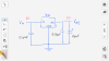
The circuit is designed by KrisBlueNZ. Very grateful to him.
**** both the circuit work very well on breadboard fyi. ****
 

Attachments

  • 20140522_171359.jpg
    20140522_171359.jpg
    226.4 KB · Views: 251
  • 20140522_171352.jpg
    20140522_171352.jpg
    185.4 KB · Views: 219
  • 20140522_170640.jpg
    20140522_170640.jpg
    120.9 KB · Views: 278
  • 20140522_170634.jpg
    20140522_170634.jpg
    142.7 KB · Views: 209
  • 20140522_170628.jpg
    20140522_170628.jpg
    118.8 KB · Views: 222
  • 20140522_170612.jpg
    20140522_170612.jpg
    97.7 KB · Views: 226
  • 20140521_224426.jpg
    20140521_224426.jpg
    183 KB · Views: 275
It just left this finishing part. It's close to a full success. I dont want it to end up with 'so close yet so far'. Your help will mean a lot to me.
 
One thing you should do is clip all the leads on the back of the perfboard. It is too easy for them to short each other now.
 
Top