Maker Pro
Maker Pro

Rain Sensor Status

Harald Kapp

Moderator
Moderator
Since you only want to light up 1 out of 2 LEDs, you can get rid of the voltage regulator and use a constant current source instead:
unbenannt-png.15176

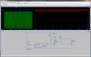
Vpower is modeled as a 10V DC source with a 2V sine rippple at 60 Hz.

D6, R7, R1 and Q4 make a constant current source. D6 keeps the volate at the base of Q4 at 4.7V below Vpower. Vbe of Q4 is ~0.7V, therefore the voltage across R7 is 4V, regardless of Vsupply. 4V/560Ω gives a current of 7mA (in the simulation we see ~6mA).

Q1 and Q2 control the current flow from Q4 to go either through LED D2 or LED D5. Q1 and Q2 in turn are controlled as in my post #4 from the 3.6V (RMS, therefore 5V peak in the simulation) Ac input.

A residual ripple on the LED current is visible in the simulation, but will, I think, be invisible in real life due to the small amplitude and the frequency (60 Hz are invisible to the human eye). In practice the ripple on Vsupply will be at at an even higher frequency of 120 Hz due to the bridge rectifier (I left out the full model for the power supply in this simulation).
 

Attachments

  • Unbenannt.png
    Unbenannt.png
    307.4 KB · Views: 214
1) you don't need an X and/or Y rated capacitor for C1. C1 is on the low voltage side of the transformer so (almost) any capacitor is suitable.
Excellent! That should be easier to source. I have seen non-polarized aluminum caps, are those ok? Or are they miswritten. I found a ceramic on Digikey rated at 50V non polar that looks good.
2) you sjould use a regulator anyway to acommodate for variations in input voltage, load, temperature etc. By lowering the input voltage to the regulator via C1, you reduce the power loss in the regulator.
Good point, just because the simulation shows a stable result doesn't mean it will remain static as input will fluctuate. I will increase the voltage to accommodate the less than 1V drop for the switching regulator. I guess now I can also simply use the LM7805 since the Vdrop won't be as significant. The min. input is 7V - to account for fluctuations would it be wise to choose 9V as the input?

By changing R4 to 330Ω I get ~9V with ~27mA - that should be more than enough power for either circuit (5-10mA quiescent current for either IC)
Thanks Harald, this is looking completely doable!
As for the other schematic, it's a bit much for me to comprehend, but I appreciate it as I will be studying the circuit as I learn more and will certainly add it to my tool box in the future :)
 

Harald Kapp

Moderator
Moderator
Non-polarized alu caps are mostly used for audio applications. You could use one here, but I recommend film or ceramic if you get the required capacitance. 50 V sounds o.k, too.

From the 9V you can regulate to 5V using a standard 7805 regulator (78L05 for small currents <=100mA, have a look at the datasheets).
As for my last shcematic: It isn't really more complex than the schematics discussed before. Q1 and Q2 make the same controlling circuit for LED1 and LED2 as before. The main change is that the voltage regaulator and the series resistors for the LEDs have been replaced by the current source around Q4. But I do not mean to force you into using this circuit. It's completely o.k. that you go at your own pace.

Thank you Harald, it looks like a winner :)
 
I had a hard time finding a model for the LM7805 in LTSpice - ended up on youspice.com and found one made by LT!
For the values below I get a clean, fairly ripple free 5Vdc output from the v-reg. The input is around 11.8V with 33mA across R4. Assuming I applied Ohm's law correctly (P=IV), .033*11.8= 0.39A - I probably should use a 1w resistor for safety.

If the AC IN falls to 24V, the same values below produce Vout of the regulator @ 4.5 +/- 0.3v.
  1. Is a +/- 0.3V ripple significant for two LED's? The D5 LED shows in the simulation about 7.8mA (at 29.2VAC in, same LED is 9mA).
  2. Should I base the C3 value off of the lower AC input to accommodate for loading of the circuit?
I don't know how much of a Vdrop I can expect from the valve manifold, I will try to get a reading tomorrow when the valve is actuating to see if there is a signifcant Vdrop.

upload_2014-9-13_21-50-10.png
 
On actuation the voltage from the transformer only fluctuates to 28.6VAC while the solenoid is energized. The system spends most of its time in the unenergized state so designing the system based on 29.2VAC seems the way to go. So I still need to know if I was correct about R4: The input is around 11.8V with 33mA across R4. Assuming I applied Ohm's law correctly (P=IV), .033*11.8= 0.39A - I probably should use a 1w resistor for safety. Is 0.39A the correct value? I am assuming that R4 is dropping 11.8v since its directly connected to ground. Thanks all!

I can not seem to find a 100μF 50v ceramic or film capacitor. I can find bipolar aluminum caps of this rating.
 
Last edited:

davenn

Moderator
hi ya :)

R4 isn't needed
C4 drop from 1000uF to 100uF ( 1000uF is way too much)
Place 0.1 or 0.01uF caps in parallel with C1 and C4

You should NOT be getting 4.5V out of the regulator unless there is a problem
ie. the voltage out of the regulator should be 5V ± 0.1 - 0.2V when the input to the reg is at least 2V above 5V

Dave

What would you recommend for the C3, the first cap that the AC runs through? I tried other values, but 100uF seems to be the value that will give me adequate input voltage to the regulator. I am having a hard time finding that size though...
 

davenn

Moderator
You shouldn't need/have one there
that is not a standard arrangement for a power supply

what do you mean adequate voltage to the regulator ?
at 28V you are almost overdriving it and its going to get extremely hot
recall what I wrote in that earlier post (post #26) about Vdrop across the reg

the 5V reg, at the most, only needs 7 - 10 V going into it

Dave
 
Last edited:
You shouldn't need/have one there
that is not a standard arrangement for a power supply

what do you mean adequate voltage to the regulator ?
at 28V you are almost overdriving it and its going to get extremely hot
recall what I wrote in that earlier post (post #26) about Vdrop across the reg

the 5V reg, at the most, only needs 7 - 10 V going into it

Dave
Yes, that is why Harald recommended the use of capacitor fed supply then use a voltage regulator to further drop and regulate. That is what the capacitor is for. My only problem was that to give a 11-12v supply to the regulator required a 100μF cap. I couldn't find any ceramic type with a 50v rating. The only ones I have been able to find where aluminum bipolar type.

It might be time to research an active zener circuit, wish me luck! LOL
 
Last edited:

davenn

Moderator
I cant find where he was referring to the need for C3 ... that series cap on the AC input to the bridge rectifier ?

can you give me the post # please

C1 = 1000uF electro
C4 = 100uF electro or tantalum stype

Dave
 
I cant find where he was referring to the need for C3 ... that series cap on the AC input to the bridge rectifier ?

can you give me the post # please

C1 = 1000uF electro
C4 = 100uF electro or tantalum stype

Dave

Post 37 - listed as C1

Dave, what is the purpose of the small capacitors in parallel that you asked me to add?
 
Last edited:

davenn

Moderator
ahhh thanks for that
I now see where Harald was going :) ignore my comments re C3/R4

Dave, what is the purpose of the small capacitors in parallel that you asked me to add?

that's really standard for linear regulator chips 78/79xx series LM317 etc

they are used for increasing chip stability .. the reg chips can go into oscillation given certain conditions
This info is in most linear reg sheets

cheers
Dave
 
ahhh thanks for that
I now see where Harald was going :) ignore my comments re C3/R4


that's really standard for linear regulator chips 78/79xx series LM317 etc

they are used for increasing chip stability .. the reg chips can go into oscillation given certain conditions
This info is in most linear reg sheets

cheers
Dave

I have seen the 0.1 and 1μF caps placed in parallel with the input and output respectively on a few datasheets. Don't C1 and C4 accomplish the same thing despite them being of larger value?
Thanks!
 

davenn

Moderator
no they don't, they are for DC smoothing only
That is because of their larger values
those values wont "respond" to the freq of the oscillations

Dave
 
no they don't, they are for DC smoothing only
That is because of their larger values
those values wont "respond" to the freq of the oscillations

Dave

Interesting, on spice, the opposite seems to be occurring in the model - higher values of the capacitors seem to smooth the DC more! Capacitors in parallel are summed anyway - I may not understand you correctly: If a large and small value are in parallel, don't the values end up just being the sum?

I assume the oscillations you speak of would be seen by me on the DC voltage scale ouput of spice, correct?
Thanks in advance :)
 

(*steve*)

¡sǝpodᴉʇuɐ ǝɥʇ ɹɐǝɥd
Moderator
The issue is that larger capacitors often have some inductance or equivalent serries resistance that will begin to dominate at higher frequencies.

Unless you give spice these values (possibly by including them as additional components, although the models may allow for ESR and ESL) then you'll just be modelling a perfect capacitor.
Thanks Steve - more than meets the eye as usual!
 
With an active zener voltage reference I don't need a cap on the AC side which makes it much easier to find the necessary parts.

When I look at the ammeter in Spice, it shows the graph below for current at C4:
There is a short peak at over 5A, with peaks settling into a pattern at 1.8A - Is this the draw on the transformer? How can I tell if this will exceed the capabilities of the transformer? Do I need to be concerned with that initial transient spike?

Can anyone recommend a good npn transistor for Q1?
Thanks in advance.
upload_2014-9-14_23-54-36.png


upload_2014-9-14_23-33-29.png
 

Attachments

  • upload_2014-9-14_23-52-21.png
    upload_2014-9-14_23-52-21.png
    128.9 KB · Views: 158

Harald Kapp

Moderator
Moderator
This peak is called inrush current. It is due to the capacitor being discharged at the beginning, so it presents almost a short circuit to the voltage source (almost, because there are the diodes, the capacitor's own series resistance, the impedance of the transformer etc.). This will lead to a current peak to charge the capacitor rapidly. Once the capacitor is charged, only so much curent flows to keep it charged.

Your supposed active zener circuit around D5, Q1 and R1 looks suspect to me. The circuit I know looks like this one (half way down the page). R1 and D5 are swapped. That makes more sense to me.
 
Top