Alternatively you can reduce the voltage after the rectifier by putting an impedance in series with the rectifier. The impedance will create a voltage drop such that the output voltage of the rectifier is lower. If you put the impedance
before the rectifier, it will see an AC current. You can then use a capacitor for impedance. This has the advantage that it dissipates much less energy as heat than a resistor. Here's a simplified example:
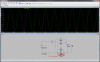
Green is the input voltage (+-30V from the transformer), blue is the output voltage across C2. By varying the value of C1 you can adjust the output voltage. Note that R2 (crossed red) is for simulation purposes only and should not be part of a real circuit.

")