I have a one man hobby machine shop. I bought a Sowon 3Kw induction heater used to heat up shrink fit tool holders. Bought it used - it does not work. Can't afford a new one. Unit blows 15 amp fuses when trying to heat the tool holder.
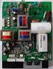
I am pretty good at building and fixing my own electronic gizmos - not so good at fixing other peoples circuits. Took the unit apart, removed the circuit board. Everything is on one board that is mounted to a large heat sink. There is no visible damage. First I checked the bridge rectifier - it is good. Next I did resistance checks on the 2 power transistors. I got: 0/0 ohms and 2.2/2.2 ohms and 2.2/2.2 ohms. I'm thinking 0 ohms is not good unless there is a transformer in parallel somewhere. I have not the traces yet. Sadly, the numbers on the transistors as well as the numbers on 4 ic's are ground off. I have no clue how to identify the transistors or the ic's. Any ideas??
I can only add a closeup picture of the transistors. No matter how I try adding a picture of the whole board always gives me an error...
Thanks, David