Maker Pro
Maker Pro

Please help a newbie connect woofer

Very important:
Don't use Chebyshev filters for speaker cros-over!
The reason being it has "ripple" in the Pass-Band which isn't what you need at all!
Use Butterworth filters (1st order)
 
Last edited:
Thanks to You, I learned so much in few days and I feel that I'm getting closer to wiring part now.


No problem, You helped anyway. While it would be convenient for this moment to get results, but I would rather learn to count them myself. Problem is that either I don't know how to look for them or google doesn't offer any usable results on this topic. If You could recommend some literature about it it would be appreciated.

As far as I understood my total system impedance won't be constant (it'll change depending frequencies playing and speakers working at that moment, right?) and since my signal overlaying (I'm thinking about 120 Hz for sub-woofer, 90Hz-1100Hz mids and 1000Hz tweeter) is not that big so I shouldn't be worrying about it and leave it be, right?

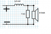
I redesigned my diagram for more simple filters, for band pass I combined RL High pass and RL Low pass filters, or for High pass I should use RC filter like in tweeter?

Also getting back to question about using resistor to correct impedance for amplifier: is it legit way? Because now I counted my other speaker impedance I got it 5.333 Omh, I would like to raise it back to 8 Omh.

And last question for now: I trying to understand Chebyshev Bandpass filter and it calculation tool (not necessary I am going to use it now, but I still like to understand it), please tell me if my observations are correct.View attachment 25331 View attachment 25330
You are correct. The NaN value means you do not use it in this application. You will notice that there are capacitors marked NaN in the same section as well.

As far as using a resistor in series with your speaker, you most certainly can... but you will need a very high wattage resistor. The power output for audio equipment can be quite high.

Dorke has a great point regarding the filter you are looking at as well.
I have a couple Wikipedia links for you to poke at:
https://en.wikipedia.org/wiki/Filter_(signal_processing)#Classification
Take a peek at the graphs they show. The simple RL, and RC filters I have mentioned do not have this little 'ripple' that dorke pointed out.

Additionally, you may not need as much overlap as you are planning:
https://en.wikipedia.org/wiki/Frequency_response#Estimation_and_plotting
When you build a Low-Pass tuned at 100Hz, the sub will still play audio at 105Hz, it will simply be quieter. The further away you move from the tuned frequency, the quieter it gets. So if you have a Sub up to 100Hz, and a Mid with a 100Hz to 1kHz range, both the sub and Mid will play a portion of the 100Hz tones at a slightly reduced volume.

As far as not being a constant impedance, you are right, but that's the case anyway... As you sweep across the frequencies the impedance will not be constant and will be lower where there is overlap in your filter.
As far as adding them together is concerned, you can use the standard 'parallel resistor' formula:
Rx = 1 / ( 1 / R1 + 1 / R2 + 1 / Rn )
So an 8Ω and a 6Ω would result in a 3.5Ω ...
Two 8Ω in parallel would be 4Ω ...
 
Thank You for Your advice, I can only guess how boring is to teach beginner with no physic background since school ( I went to chemistry) but You still doing it, really appreciating it .

As for my project, I feel like I need to recalculate my tuning to frequencies overlap little less and I am good to try to wire everything together, right?

I tried this formula, in my case if mid overlaps with tweeter or sub-woofer, I get 5.33Ω. I am interested in the fact at what point this became a thing I should be concerned about. Should I avoid overlapping frequencies at all and tune all the speakers like this: sub woofer- 100Hz Mid 100Hz-1000Hz and tweeter 1000Hz since, like You mentioned before, they going to overlap anyway, but just play little bit quieter. Or I can overlap signal a bit and don't worry about impedance I get from standard 'parallel resistor' formula. It's that the case, I'm interesting there is the limit for overlaying. Are there some way to calculate, use some tables or it's jus trial and error and personal experience way?
The audio guys may be able to help you with that... I can't begin to tell you how much overlap is acceptable, so I would personally build mine with no overlap. Design the filters for cut-offs at 100Hz, and 1kHz and call it done.
It's not good for the amp to run with an Ω lower than it's rating. It stresses it out. I chose my words carefully here... it may not cause a direct fault, but could lead to a failure sooner than expected. If you would like to know why, take a look at a resistor series circuit.

Source > (Internal Impedance) > Speaker Impedance > Ground.
If your source is 24V, you will find that you get the most power to the speakers if the impedance is matched. If the Speakers are too low, the power dissipated internally goes up. Of course there is wiggle room here. If the Speakers are too high, then the power output is usually just less and you get no problems. (However, TUBE type amplifiers MUST be matched... Solid state is more forgiving)

Now.. I'm curious here what formula you used for find 5.33Ω ?
 
Thanks, I'll just do like You say then and don't have to be afraid that my amplifier going to burn after longer period of working. And in the future it's probably a good idea to buy amplifier with bigger impedance tolerance range, or try to combine different resistance speakers...

As for formula: I used, I believe it's the same as You posted:

R= 1/(1/R1+1/R2+1/Rn), but since my mids connected in series and I counted that they will overlap with either sub or tweeter, but not both so I got values: R=1/(1/16+1/8)= 1/(0.0625+0.125)=1/0.1875=5.333Ω
Did I used it correctly?
I didn't realize you used two mids in series. That equation is correct. Your new speaker setup should have an impedance range of 8Ω to 5.33Ω, but the 5.33Ω is unlikely if the chosen cross-over frequency does not have un-impeded overlap. Additionally AT the cross-over frequency of 100Hz where the Sub AND Mids will both operate, the Inductors and Capacitors in series with these speakers will be acting as resistors, so the estimated 5.33Ω will actually be higher than expected, and would only apply in the near frequency range of your 100Hz and 1kHz cross-over frequencies.
 
So I tried to wire everything together. Here are the results: leds part works like charm, they shine even with pretty low volume. I'd call it success. As for the speakers part it more or less work, but it encountered problems and raised more question.

First of all, electronic store did not have exact components I needed, so they gave close ones (in values) as needed. As a result cut off frequency got higher than I wanted (fixable with correct components).
Problem is that after wiring and testing my sub-woofer played, what I think is all frequencies, while mids and tweeter barely played at all. After quick investigation I noticed what I probably wired wrong inductors . Please take a look at my scheme and confirm is that a case.
mano sujungta test.png
Second (huge) problem I encountered that resistors and inductors started to overheat rapidly. Can it be because in electric store they gave me 10 W resistors? I wasn't quite sure what kind I need (my amplifier gives 40 W per channel), so I just asked to give ones vendor thinks are best (I told him my amplifier wattage). So turns out I needed 40 W resistors, or there are some kind of formula to count needed resistor wattage?

Third problem, I tried to test my theory about incorrectly wired inductors, so I rewired sub-woofer filter and quickly tested only it. As a result sub-woofer played less higher frequencies (so that proves my theory?), but I noticed that it played noticeably quieter than it should, and also resistor and inductor got really hot quick so I had to stop test. Could it be because poorly chosen resistor? komponentai.jpg
 
So I tried to wire everything together. Here are the results: leds part works like charm, they shine even with pretty low volume. I'd call it success. As for the speakers part it more or less work, but it encountered problems and raised more question.

First of all, electronic store did not have exact components I needed, so they gave close ones (in values) as needed. As a result cut off frequency got higher than I wanted (fixable with correct components).
Problem is that after wiring and testing my sub-woofer played, what I think is all frequencies, while mids and tweeter barely played at all. After quick investigation I noticed what I probably wired wrong inductors . Please take a look at my scheme and confirm is that a case.
View attachment 25348
Second (huge) problem I encountered that resistors and inductors started to overheat rapidly. Can it be because in electric store they gave me 10 W resistors? I wasn't quite sure what kind I need (my amplifier gives 40 W per channel), so I just asked to give ones vendor thinks are best (I told him my amplifier wattage). So turns out I needed 40 W resistors, or there are some kind of formula to count needed resistor wattage?

Third problem, I tried to test my theory about incorrectly wired inductors, so I rewired sub-woofer filter and quickly tested only it. As a result sub-woofer played less higher frequencies (so that proves my theory?), but I noticed that it played noticeably quieter than it should, and also resistor and inductor got really hot quick so I had to stop test. Could it be because poorly chosen resistor? View attachment 25350
Looks to me like it was initially wired incorrectly as well.
The 1.0mH Inductor and the 1Ω resistor should be used on the Sub to provide a Low-Pass filter around 160Hz.
Using a 0.1mH will allow higher frequencies through which is what you witnessed.

The red-lines wont made a difference, and the power through the components will make them toasty, but should not 'hot'.
Can you share the resource you used to make the filter and choose the values?
 
Have you looked for online calculators for crossovers? I am sure I have seen such a thing before.

Bob
 
Well, I used online calculator for calculating filter values, initial idea was to make sub-woofer cutoff at 100 Hz, but since store did not had resistor I needed (0.62Ω), I bought closest possible (1Ω). It raised cutoff frequency from 100 to around 159 Hz (according to online calculator).
I realized that I wired wrong after first test (sub-woofer played all the frequencies). I made beginner mistake here... After separating components and quickly building correct filter just for sub-woofer I got expected result (sub-woofer played only lower frequencies), but problem that it played really quietly compared to no filter at all.
And the thing with component overheating... I realize that they going to be warm, but they became very hot (can't hold them with bare hand hot and inductor plastic showing first signs of melting hot), I don't think its normal. So could it all be (low speaker volume and components overheating) because resistor was only 10 W while my amplifier gives 40 W?

For calculations I used this site: http://sim.okawa-denshi.jp/en/CRlowkeisan.htm
 
You do realize that the resistance in the simple RC or RL filter is the speaker itself, right?

Bob
 
I did not get the question completely. You are talking about total impedance my amplifier will get from filter/speaker setup? I realize that filter have little impact on that. Or You are meaning to say that I need to use that resistance in formulas I am using for this filter?

I am trying to understand how to calculate needed resistor wattage. But I have some troubles understanding equations. Here what I got from some tutorial:

In order to calculate the wattage we need to know the voltage and the resistance also we need the formula for power
which is P(power)=V(voltage) * I(current)
As we see we already have the voltage, so we need to find the current. From Ohm's law R(resistance)=V(voltage) / I(current)

we transform the formula to I =V / R
so the power formula becomes

P=(V *V) / R


Everything seems easy enough, but I do not understand where to get voltage. All I managed to find about my amplifier is this: Power output: 40 watts per channel into 8Ω (stereo).

So using formulas I have I can calculate amplifier voltage, am I right? It would be like this:
(V*V)=P*R
V^2=P*R
V= P*R

V=√ 40*8=17,88 volt

Now I have voltage and I can count exact resistor power needed?

If I understood Bob correctly, so resistor wattage needed is:

P=(17,88*17,88)/8= 37,76/8=4,47 W

Since I found recommendations that resistor should be at least twice bigger than its actual needed power, so 4,47*2= 8,94 W
In conclusion 10 W resistor is more than enough in my case?

Are my calculation correct, or I completely misunderstood something?
 
UPDATE:
Today I tried to repeat test I perform yesterday, hoping to make some new observations. For this test I connected everything like this:
: testas.png
Results:
According to my online calculator (http://www.learningaboutelectronics.com/Articles/Low-pass-filter-calculator.php#answer2) filter cutoff frequency is 159 Hz, judging from the sound speaker made its should be more or less correct. (still it played very quietly)
I fried my inductor... There was smoke, smell and melting plastic. Now I am 100 percent sure components were overheating.
sukepęs induktorius.jpg

By doing this test I noticed interesting thing, one om my used online calculators resistor resistance write: 0,62Ω while another gives no result then I put this value. It only gives result with 620Ω. Why it is so?
Also I noticed that my used resistor is not 1kΩ, but only 1Ω since when I bought components I used 0,62Ω and got closest possible 1Ω. SO could it be the problem I encountered rises from poorly chosen resistor?

My resistor:
resistorius naudotas.jpg

It is only 1Ω right?
 

Attachments

  • testas.png
    testas.png
    8.5 KB · Views: 43
What I am saying is illustrated by the circuit you posted. You are calculating the frequency as if the R is 1000Ω. But it is in parallel with the speaker, which is 8Ω, giving you a total resistance of 7.93Ω. The 1K resistor is basically doing nothing in this circuit. And the cutoff frequency is actually not 159Hz but 1.27 Hz.

It is actually much more complicated than that, because the impedance of the speaker is not a pure resistance, it is a combination of resistance and inductance.

Find a tool that is specialized for designing speaker crossover networks.

Bob
 
Time for me to hide in a hole. I was so focused on showing you how these filters work in the first place, that I completely spaced and forgot to account for the speaker's attenuation when choosing the Capacitor and Inductor values.
You should only need 2 Inductors and 2 Capacitors. Resistors only for correcting impedance.
 
I played with the calculator a little.

The bandpass gain is something they calculate and it only applies to second order or higher filters. It is not clear to me what it means.

Higher order filters give sharper cutoffs, and therefore less overlap between the different drivers.

Bob
 
Thank You for the help

In this case I will try to keep as low as possible when just to be sure.

I was planning to cut sub-woofer at 100 Hz and tweeter at 1000 Hz, but calculator only let me do cut at 800 Hz for tweeter when I choose sub-woofer value of 100. Any particular reason for this or jus calculator designed this way?
 
Yes, because the bandpass is set at 3 octaves, it cannot handle 100 to 1000, only 100 to 800 (which is 3 octaves.)

Choose the spread to be 10 3.4 Octaves, and it will allow it.

Bob
 
Thank You very much,
since only tomorrow I can get my hands on my set up again and try to wire everything together I keep studying info I can find. And I read that it is better to keep tweeter above 1kHz, is it true?

Also I having trouble understanding Notch filter and its usage with tweeter. According to example I found tweeter's Fs is 1000Hz (free air resonance of tweeter is info I should get buying tweeter or it's something I can count?), crossover frequency 3000Hz and resonance spike is over one octave from it, but despite that fact they still building Notch filter, just to be sure.

The thing I don't quite get- what is this resonance spike they trying to reduce? As far as I understood it gives amplified response at that frequency and tweeter sound louder than at others frequencies thus sounding unnatural and out of order? Am I right?

 
Top