Maker Pro
Maker Pro

PIR operated DC motor project odd behaviour help

Exactly as you predicted
12v before i short them
And 0 when i short them,also motor starts turning when i short them and both LED-s are lit.

Ivan
 

CDRIVE

Hauling 10' pipe on a Trek Shift3
Here's another test:

(1) Divorce the GSM from the Timer board.
(2) Power up the Timer board.
(3) Monitor the Opto + - input with your DMM
(4) Momentarily short the Opto + - Input.
(5) Make note of voltage reading immediately after opening the short.

I would expect ~+12V when open and ~0V when shorted.

If all else fails post a clear photo.

Chris
Exactly as you predicted
12v before i short them
And 0 when i short them,also motor starts turning when i short them and both LED-s are lit.

Ivan
You forgot #(5). It's important! Also, is it timing out as it should?

Chris
 
It rises to 12v as soon as i open the short
It shows 8-9v and than 12v on DMM.
Yes, timer is set to turn off motor after 2-3 seconds
 

CDRIVE

Hauling 10' pipe on a Trek Shift3
It rises to 12v as soon as i open the short
It shows 8-9v and than 12v on DMM.
Yes, timer is set to turn off motor after 2-3 seconds

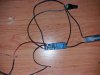
No surprises there, so something else is amiss. Logically it would point to the 2N2222 basing. Please post a clear photo of the GSM - 2N2222 - Timer interface.

BTW, why are you testing this with the timer's timeout set to only 2 seconds? I would think that the GSM's vibrator output has a pulse width of at least one to 2 seconds each time it (goes high) rings.

Chris
 
Here are the pics
if there are any details left out i will take more pictures
this is only wiring for testing
finished this will look much better
 

Attachments

  • IMG-2c505787d8cab8360cd3aa19f4345770-V.jpg
    IMG-2c505787d8cab8360cd3aa19f4345770-V.jpg
    144.2 KB · Views: 105
  • IMG-776130fe7c823a988d6d06b7aa18454a-V.jpg
    IMG-776130fe7c823a988d6d06b7aa18454a-V.jpg
    160.5 KB · Views: 99
  • IMG-cbe074f600573367308ac8ad13bd6330-V.jpg
    IMG-cbe074f600573367308ac8ad13bd6330-V.jpg
    161.1 KB · Views: 100

CDRIVE

Hauling 10' pipe on a Trek Shift3
Despite the fact that using all black wires is bad practice (the source of many "Oh sh!t" moments) I don't see anything wrong there. Admittedly, my old eyes suck!

Measure the voltage between the base and emitter while it's ringing. It should swing from near 0.0V to ~ .65V upon each ring.

Chris
 

CDRIVE

Hauling 10' pipe on a Trek Shift3
A thought..... Have you ever measured the vibrator output voltage with the vibrator motor disconnected? I'm taking an educated guess that you'll find it doesn't drop to 0.0V when not loaded. If so connect the vibrator motor and test the timer again.

Chris
 
I never used vibrator motor,i disconnected it straight away,only used the wires,and i dont have that tiny motor anymore,can i use resistor instead ?

measured base-emiter voltage,0.64 constant when it is not ringing and 0-0-7 pulses when it is ringing

Ivan
 

CDRIVE

Hauling 10' pipe on a Trek Shift3
I never used vibrator motor,i disconnected it straight away,only used the wires,and i dont have that tiny motor anymore,can i use resistor instead ?

measured base-emiter voltage,0.64 constant when it is not ringing and 0-0-7 pulses when it is ringing

Ivan

That is contrary to what you posted earlier. If the base -emitter junction never goes to 0V then it's not logical that the vibrator output does. What does the vibrator output measure when not ringing?

When it Is only powered on but not ringing
When i connect (-) from DMM to it's battery and measure voltage on both + and - output i get 0v.
When it is ringing i get 0v on (-) and 3.30v to 0 intervals on (+)
Yes, a resistor would be better. Better yet,.. do you have a Red LED? If so connect the LED in series with the 1KΩ base resistor. The ~1.9V drop of the LED will probably solve the problem. Anode to GSM ringer (+) and Cathode to the 1K.

FYI: A DMM is not a reliable instrument for measuring transient DC voltages. Oscilloscopes are used for such.

Chris
 
Top