Maker Pro
Maker Pro

PCB Layout Help

Hello,

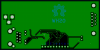
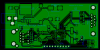
I am designing a board with an ATSAMD20 microcontroller and the ENC28J60 Ethernet PHY with some additional things. The issue that I have is the 25MHz crystal oscillator will not start up. When I probe around the crystal I see a very noisy 52KHz sine wave. Is it possible the SMPS on this board is introducing to much noise and is preventing the crystal oscillator from starting? I have attached gerber files of the board. Any help would be very much appreciated, even general feedback about layout of the board or anything.

Thank you.

JD
 

Attachments

  • Gerbers.zip
    40.9 KB · Views: 116
Hi JD and welcome to electronicspoint!

We can have a look at your PCB layout but better to start with the schematic. Can you please post it ?
Also the ENC28J60 as a clockout pin where you can measure the 25Mhz clock divided by 4 (default value).

Olivier
 
Hi Olive,

Thanks for the reply. I have attached the schematic as a PDF. I appreciate the help.

JD
 

Attachments

  • EthernetBridge.pdf
    71.6 KB · Views: 176
The ATSAMD20 as a quite complex clock circuitry, do you succeed to make it work on is internal 8Mhz oscillator first?
Also you are using the clock
generator to produce 25MHz to the enc28j60, is the clock generator able to divide by 1? I have seen a minimum of 8 but just have a quick look on the datasheet.

Olivier
 
Last edited:
Hi Olive,

The ATSAMD20 does run fine on the internal 8MHz oscillator. I don't know if [pretty sure I can't] use the DFLL to generate the 25MHz ethernet clock. That said I was planning on clocking the entire system at 25MHz and using the generic clock 0 output pin to clock the ENC28J60. The ATSAMD20 can output the generator clock on certain pins if enabled. According to what I've seen and read the clock dividers can be set to divide by one. The real issue is that when I scope the crystal output I don't see a 25MHz signal at all. I can see alot of noise of about 80-100mV with spikes that correspond to a 52kHz frequency. I'm concerned that the power supply (LM2575) is introducing too much noise in the system and is preventing the oscillator from starting correctly. I'm a self taught electronics guy and, sadly, my understanding of EMI and PCB construction is lacking. Is there anything that stands out to you about my design? I can attach the KiCAD PCB file if you want it.

Thanks so much for your help.
 
Hi Arouse,

Please see attached board plots. Thanks for your assistance!

JD
 

Attachments

  • BoardBottom.png
    BoardBottom.png
    23.9 KB · Views: 224
  • BoardTop.png
    BoardTop.png
    57.6 KB · Views: 533

KrisBlueNZ

Sadly passed away in 2015
What is the manufacturer and the complete part number for the 25 MHz crystal you're using?

Have you tried another crystal? Either the same manufacturer and part number, or different? Or are you still using the first crystal you've tried? Have you tried more than one board?

Are you putting your scope on the signal at the crystal? Have you tried scoping the divided-down output?
 
Hi Kris,

I have tried two crystals. First one: Abracon ABLS-25.000MHZ-B4-F-T, the second: ECS ECS-250-18-5PX-F-TR. I have not built up another board yet, as I don't have all the parts on hand to do so at the moment. I am scoping the generic clock output from the microcontoller and I have probed the crystal input on the micro as well. I did experimentally try probing the crystal directly, and still saw no oscillation at all.

Thanks!
 
To me the problem is more located on the ATSAMD20 system clock configuration.
Have looking at you gerbers and the layout looks OK. The 52Khz from you regulator should not be the root cause to me.
You can have two issue:
Correctly set up the ATSAMD20 for an external crystal
Correctly set up the clock system to generate the 25MHz on the dedicated I/O

Better to be focused on the first issue, however knowing that the internal oscillator works fine you can try to generate a 8MHz or lower clock based on that oscillator to ensure that this code part is correct. It's better to probe the signal at the divided-down output, as suggested by Chris, probing the crystal pins can give unexpected results.

Olivier
 
Is the 25MHz crystal usage even possible? The Atmel ATSAMD20-XPRO board is using a 32KHz (RTC) crtystal on the concerned pins.
Olivier

EDIT: OK misreading on my side you are using the XOSC pins, not the XOSC32K ones, that's OK.
 
Last edited:
Hi everyone,

I'm pretty sure that the software is correct to enable and use the 25MHz crystal. I can see the 8MHz signal with my scope on the generic clock output pin when I run on the internal oscillator. It may have been possible when I was scoping the crystal input pins that I briefly connected XIN and XOUT through the scope probe. Would it be possible that I damaged the crystal driver circuitry in the SAMD20 this way?

Thanks,
JD
 
I think your right about the noise from the switcher. Your crystal layout has some issues. Noise could be quite easily coupled onto these lines, they run very close to the ground plane which could have switching noise on it. Also the top crystal track runs very close to a track from U3 which is the power supply. This could couple noise from the switching of this device. Here is a better layout. You sometime need a guard ring around crystals when using double sided PCBs, I never use them because my PCBs have internal power planes.
Adam

New Picture (3).png
 
Yes I will try that. I need to build up a new board, and I will not populate the power supply parts. I'll post back once I get the parts in.

Thanks!
 
Arouse,

Thanks for the example layout! It's very helpful. I have a question, just for my own edification. Assuming that there is approx. a 100mV 52KHz signal being coupled into the oscillator trace that runs by that supply trace, how likely is it that the noise is preventing the oscillator from starting?

Very likely.
Thanks Adam
 

KrisBlueNZ

Sadly passed away in 2015
Assuming that there is approx. a 100mV 52KHz signal being coupled into the oscillator trace that runs by that supply trace, how likely is it that the noise is preventing the oscillator from starting?
It's going to depend on the higher-frequency components in the 52 kHz signal. A 52 kHz sinewave will have no effect, but a 52 kHz square wave with rise times in the nanosecond range certainly could have an effect. But Olivier's suggestion is the right answer - eliminate the switching noise and see whether it works.
 
Top