Maker Pro
Maker Pro

not starting bldc motor

hello engineers
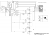
I want to start up a bldc motor by the hahh sensors & PIC micro for using in electrical bike.I want to make it's control circuit myself. I have used IR2110 & IRF mosfet for high ampere part...I connected the circuit but the motor doesn't move at all.why? please help me...please
 
I connected the circuit but the motor doesn't move at all.why?
Because either the circuit or its connections or the PIC hardware/software is/are faulty or the battery is dead :rolleyes:.
Without a schematic and full details of your setup we're unable to offer help.
 
Because either the circuit or its connections or the PIC hardware/software is/are faulty or the battery is dead :rolleyes:.
Without a schematic and full details of your setup we're unable to offer help.
this is almost my circuit...ofcourse i have used IR2110 & related circuit instead of 2N2222A transistors
thanks
 

Attachments

  • circuit picture.png
    circuit picture.png
    215.3 KB · Views: 264
  • 2110BLDCSchematic_zps9d5a0550.jpg
    2110BLDCSchematic_zps9d5a0550.jpg
    41.2 KB · Views: 164
since I have totally 5 outputs from motor so that its 3 outputs is related to sensors(of course I think ).so I at all have'nt used comparators
an other thing, the capacitors attached to IR2110 circuit are 33uf & 100nf
 
in your oponion, how can I test the IR2110 circuit that I send it at the before posts (of course I don't have accesss to osciloscope)....please help me
 
I mean this circuit...How can I test it?
thanks
 

Attachments

  • 2110BLDCSchematic_zps9d5a0550.jpg
    2110BLDCSchematic_zps9d5a0550.jpg
    41.2 KB · Views: 91
Set up the circuit as shown,
connect a 12V rated incandescent lamp as a dummy load,
connect +12V to +Vdd, +Vcc and +MOSV,
apply logic-level pulses of several kHz repetition frequency to HIN and LIN,
vary the mark/space ratio of the pulses and see the effect on lamp brightness.
Note: HIN and LIN must be in anti-phase and non-overlapping, otherwise the MOSFETs will fry.
 
"apply logic-level pulses of several kHz repetition frequency to HIN and LIN" , what do you mean?
at the moment I have used PWM as an input to AND gate along with A,B,C high that come from the micro
can I use this PWM wave for apply the same frequency that you mentioned...how can i give this PWM wave to HIN & LIN so that they are anti-phase & non-overlapping ...and then if the lamp is bright,it wil mean the circuit works truly?
do i say the truth?
 
The PWM from the micro is a series of logic-level pulses, but applying them to AND gates (I assume you are now referring to those in the post #4 .png circuit) won't necessarily give the non-overlapping relationship needed to give a dead-time when neither the high-side nor the low-side FET is on. That must be ensured by the software producing the pulses. I'm no software expert so can't advise on that.
If you do drive HIN and LIN correctly then varying the PWM duty cycle should vary the lamp brightness.

Edit: Here's a pic showing (in blue and yellow) antiphase but overlapping pulse trains (bad) and (in red and white) antiphase non-overlapping pulse trains (the sort you need for HIN and LIN).
Hin&LinPulses.JPG
With reference to the post #4 .png circuit, providing the micro is correctly programmed to give a dead-time between the Ahigh and Alow signals so that they are non-overlapping, then the output of gate AND-A could be used for HIN and the signal Alow could be used for LIN when testing the post #10 circuit.
 
Last edited:
hello freinds...
I could start up the motor without using the sensors;) (of course motor doesn't work completely continuous and the speed was very low & there were quiet short stops beetween every rotation )
anyway leave it...
when i want to start up the motor with the sensors,it doesn't move at all...it's interesting that the micro can read the sensorso_O..apparently high power part of my circuit works truly..:confused:
how should i do? :(
 
Top