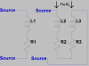
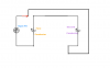
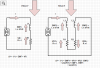
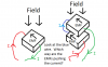
Thanks for the suggestion. I've used it for the attached diagram.
If there were any changes in the current I, then you would be correct that the reactance of both inductances would add in opposition to the change in the current. But if we are assuming the current is constant, then the only EMFs generated are a result of a change in the magnetic field. Since the magnetic field is in the opposite sense in each inductance, then the EMFs are in the opposite sense - as shown by the arrows. The PDFs generated in the (Ohmic) resistances always act to oppose the current (again shown by their arrows.)
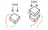
So by having two slabs in the same magnetic field, but with the current passing in opposite directions, you get twice the resistance, but the EMFs generated by changes in the field oppose each other and exactly cancel out.
In practice of course it might be difficult to ensure the field through each slab is *exactly* the same, but it should be possible to get very close. Helmholtz (See
http://en.wikipedia.org/wiki/Helmholtz_coil) realised this and devised a system of using two "ïdentical" coils, fixed symmetrically one on each side of the device under test. In your case, if the slabs are one on top of the other, the coils would be one above and one below, to make the whole apparatus symmetrical about a horizontal plane between the two slabs.
BTW I have not added many comments, but I have been trying to follow this thread and it has given me much pause for thought. Sometimes we think we understand something, until someone asks a "silly" question, or refuses to accept the "öbvious" answer, then you find yourself (or at least I do) analysing your ideas, trying to break them down into simpler steps to make a clear and convincing argument. That's when you find the gaps & flaws in your own understanding.
Although it's not germane to this question, trying to answer it has led me to Faraday's rotating disc paradox, which I had not met before.
http://en.wikipedia.org/wiki/Faraday_paradox
Also, though I think you simply cannot have a truly *constant* current generator, any more than you can have an irresistible force or an immoveable object, I am provoked to consider how I would calculate the response of a regulator to variations in load, particularly in the time domain. In the past I had just assumed that if I could plot the graph of the output for various steady loads and I put an array of capacitors (big ones for the LF and smaller ones for higher frequencies) then all would be well.
So whatever your reasons for asking, I think there is some value in trying to answer.
")