Ok I think I finally understand, so if I just copy that last section two more times over (for 3 total outputs) and use the resistors you recommended earlier (22k and 220K) i should be good to go? (adding in the stuff on the inputs such as the voltage reg, the 1volt IC chip and the two capacitors)
For the 24V supply I could use 2 12 volt batteries but as they are big and bulky could I use 3 9 volt batteries and then attached a 24V voltage regulator?
Finally because Im using the IC chip to limit the Voltage to 1V for the reference voltage do I need any resistors on the input side of the LM3914? And how do I calculate the size of capacitor I need for the voltage regulator?
You will also need a resistor or two for the 'brightness' setting on the chip, this controls the current output of the LED pins, and was recommended that you pre-set it to a high value, then you can adjust afterwards.
For the 24V supply, you will be drawing 50mA per tier it looks like, so the peak draw will be 150mA.
The 9V batteries you plan to use range from a 400mAh to 1200mAh capacity, which means you can light the entire tower anywhere from 2.5 hours to maybe 7 hours if you buy the expensive Lithium based batteries.
The 12V Lead Acid batteries are bulky, but for good reason; they have a LOT more capacity. You could also look into purchasing the 12V version of the tower instead of the 24V version. This would give you more freedom when selecting a battery or battery pack. (8 AA batteries for example)
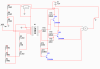
As far as the input side of the LM3914, there are 'two' inputs you need to worry about.
The signal input does have a maximum current input limit... how are you making your signal, we 'may' need a resistor on the input.
The Voltage reference input. This one does not need a resistor unless you want to adjust the input voltage... The reference voltage IN pin is quite literally just connected to resistors internally. Totalling 10kΩ . This is why you could use a little math and make a voltage divider to provide 1V instead of a dedicated chip. Of course, this is your call based on the accuracy you require.