Thanks, I've been obsessed with it and haven't had much sleep since I started.
I know that feeling! I'll PM you my email address. Please feel free to ask me anything. I would be happy to help. This sort of stuff was my job for 20 years!
I ran into a lot of problems trying to do too much inside my interrupt. I still don't quite understand the USART completely.. I guess if you don't grab the bytes from RCREG right away, you lose them.. or if you don't respond to RCIF right away you lose them. Thats' a gray area for me and was a challenge.
Yes, you have to service the USART receiver before the next complete byte is received, otherwise you lose data. At 9600 bps asynchronous, if the GPS device is sending bytes end-to-end (and you can assume that it does), the minimum byte-to-byte time is 1042 microseconds, so that's how long you have to read the received data register, from the time the interrupt is signalled. If you don't read it by then, a byte (either that byte, or the next byte, depending on the design of the USART), will be lost.
The other challenge was some situations (like incoming SMS messages) come in in two lines.. I was resetting the buffer index after every cr/lf..That was a problem because the first line was the incoming SMS message ID with the senders phone number, which I needed in order to auto-respond to them.. and the next line after the cr/lf was the message itself that I needed. So in some cases I needed to capture 2 or more lines of text and in other cases I only needed one line. I solved it by checking the first few bytes for the incoming message and then using a linefeeds counter to determine how many cr/lf's to capture beffore setting terminating the input stream with a '\0'
You can generalise the design a bit if you want to. If the first character of a line is not a letter, treat it as a phone number. You can pack two digits into each byte of storage using four bits to represent each character: values 0-9 represent the digits, and other characters such as "+" and possibly "-" which might appear in the string can be coded as 0xA, 0xB etc, or just thrown out, if the phone number string is always in a standard format. The end of the number could be marked with a 0xF nibble. Or you could use a nibble of 0x0 to signal the end, and use values 0x1 to 0xA for digits 1-9 and 0. Then set a flag saying that there's a valid phone number. When the subsequent line has been received, check the flag, and report the number to the mainline.
You should be able to calculate a maximum length for the number string. Assuming a three-digit country code, three-digit area code, and nine-digit number (which seem like reasonable maximums for the foreseeable future), you need fifteen digits and a terminator, so eight bytes should be enough.
And the more I did in the interrupt the worse things got. and strstr's and strchr's were eating up too much time so i ended up doing if(inputBuffer[0] == '+' &&... to deal with it.
Personally I prefer the idea of matching the text strings as they are received, rather than storing them in a buffer - at least in a simple application like this. It saves RAM, obviously, which is in pretty short supply on the small PICs, but most importantly it spreads out the workload over several interrupts, instead of concentrating a multi-character comparison (either explicit, or with strcmp()) in a single interrupt.
On pointers, I had a terrible time in MPLAB's debugger trying to look at pointer values and it was always not what I was expecting.. That is one reason I quit using them. I use them a couple times when passing strings to functions but thats about it.
I can't comment because I haven't used MPLAB.
Also,I read that pointers on the PIC are 16 bits long it's only an 8 bit processor. This means means that things like pointer addition (ptr++) actually takes two instructions.
If the PIC has 256 bytes of RAM or less, and code can't be accessed through pointers, pointers would only need to be eight bits wide. If they're 16 bits wide, my guess would be that the compiler would treat bytearray[n] the same as *(&bytearray[0] + n) so 16-bit pointers would be used anyway, even though no pointer variables are declared. But compilers for highly constrained architectures often use target-specific and non-standard tricks to improve efficiency, so you may be right to assume that bytearray[n] will generate more efficient code than a *cp access. You would have to look at the assembly language output to know for sure.
Edit:
Of course, pointers need to be able to point to immutable (const) initialised data in the code space. RAM is so highly constrained that immutable data will not be copied into RAM; it will reside in Flash ROM at runtime. So you're probably right. Generalised pointers will need to be 16 bits wide, even if there's 256 bytes of RAM or less, because they need to be able to address either RAM or Flash ROM, but when the compiler knows that you're addressing data that's in RAM, it can probably take a shortcut and use an 8-bit address.
I'm not familiar with the memory layout of the PIC but I'm pretty sure you can't access RAM and Flash ROM in the same address space through a simple pointer; I suspect the compiler must generate code to handle dereferencing of a generic pointer according to whether it addresses RAM or Flash ROM.
Not that I care that much I'm running at 4mhz and its plenty fast enough. I thought about bumping it up to 8 though thinking it might make dealing with the USART easier but then I figured it wouldn't matter much since its running at 9600 baud.. But again, gray area for me..
I don't understand what you're getting at.
Yeah I am using the free version of the High-tech compiler. When I was at about 98.9% full I thought about diving in and getting the pro version but then I found out it's $1,000.00 so I decided to just tighten up my code. Reminds me of how it was back in the 80's when you really and to pay attention to your memory usage. I can't believe some of the things the game programmers pulled off with 4K or less back then.
Ah yes, those were the days
")
When programmers were REAL men. Or REAL geeks
I've posted a blog page that gives the basic rundown in non techy terms of how the thing ended up here:
www.retrocell.net
That sounds interesting. I'll check it out when I get my full speed broadband back. Somehow I always seem to hit my data limit a week or two into my monthly allowance, and I have to limp by on 64kbps for the next two or three weeks :-(
I'm about ready to send my eagle files up to
http://oshpark.com and get some boards made. That will be a first for me too.
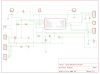
Perhaps you should post your schematic here before you send it off for manufacture, so we can check for obvious problems.
My board has no .1uf filter caps anywhere and only 1 or two pull-up resistors but its all working ok. I'm not sure about when and where I need caps. I think they are usually .1uf. and pull downs pull ups, I think I am ok with using the weak pull-ups on RB. I am using RA for outputs mostly.
You should definitely have a decoupler across the PIC, at least.
I need to wrap this project up, get back to real-paying gigs before they all fire me!
Are you doing this for your employer?
And then I've got another project in mind that involves controlling servos from a pic so I have to learn how to do that next. I guess its PWM so I just oscillate a pin on and off to drive the servo. I might use a GSM again too I like the idea of controlling things with text messages.
That will be interesting