Maker Pro
Maker Pro

Need help with LDR circuit

https://imgur.com/gallery/ZjTdqnXI am trying to create a simple circuit that will turn on an led in darkness.
Many dummy security cameras are sold with this circuit, there is a single red led and an LDR combined with a resistor and transistor
I tried something like this I saw on You Tube but when I put it all together it worked backwards , light would go off when LED covered?
I did a drawing of the circuit. Any help appreciated. Thanks
2kqmtsX
 
Last edited:
I now have a link to the photo of the drawing in the first link.
I am just looking for a general direction of the orientation of this circuit. A power source, and ldr and an led. which is illuminated when light is absent. Just took a short video of this one I took out of a dummy camera
 
well I think I found the answer to my question ...the circuit I wanted required a PNP where I was using an NPN transistor
You got to do the work to get to the bottom of these questions the slow plodding thoughtful work...but it is a mild endorphin rush when the problem solves :)
 
Last edited:
Your schematic shows an LDR (not an LED) that turns off the NPN transistor and LED strip when the LDR has light on it.
Then the LED strip turns on in darkness which is what you want.
 

bertus

Moderator
Hello,

I have resized and cropped your image:
fritz ldr schematic cropped2.jpeg
Be carefull not to turn the pot all to 0 Ohms. It will destroy the transistor.

Bertus
 

Attachments

  • fritz ldr schematic cropped.jpeg
    fritz ldr schematic cropped.jpeg
    69.8 KB · Views: 6
Both if your circuits do the same thing. When the LDR has light on it then the transistor and LED strip turn off. When you cover the LDR then the transistor and LED stop turn on.

Your circuit is wired wrong tor it to operate backwards.
 
no it did not work that way with the first drawing. I will make another one and then take a video of it to show you tomorrow
 
Sir fritzdecat . . . . .

I think that with a circuit talk thru, that you might then FULLY understand that circuit.
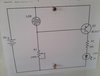
I'm using Bertus- es- es- es # 10 posts picture
Look at the extreme outer wiring loop that starts with the battery + to go up to the top and then turn right to go across to the corner and then down to the the emitter of Q1 (*****) then it continues thru the transistor and comes out the collector and then passes down to R1.
Now R1 has a computed resistance value, such that its value will not let enough power pass on thru the LED , such as to ever overload it.
Now continue with the loop on thru R1 and LED and then down and turn to the left and then finally go up, until ending at the battery - terminal.

Now we need to acknowledge the above cryptic marking of (*****), as that was being at the circuit tracing instant, where there needed to be ~0.6---0.8 negative vdc present at the base of Q1 for your wiring loop to be able to conduct / pass thru Q1.
Should you want to meter that, you use Q1emitter for - meter lead referencing and + meter lead to he Q1 base,now, if you are having an auto ranging meter it reads out correctly. . . . . or . . . . . if having a simpler meter, just get an upscale reading on the meter and the leads will then be correlating their color coding with the circuitry polarity.

Now here is how you get that base voltage level set up.

You have the R2 wiper initially adjusted such that it has the whole 100K being across its extreme ends. Then trace the path from the battery negative to the bottom of R2 and then up and thru its 100,000 ohms and then further up and turn right until you reach the base of Q1.
Look at the other possible circuit path of battery + into LDR and out of it down to the R2-Q1 base common junction.

Now, here is how to adjust R2.

You said / desired that at night / dark onset that the units LED will be LIT and then at SOME particular level of sunrise illumination, the LED will go off.

So here is how you simulate that , first you need to make it DARK by covering up that LDR sensor.
Now you need to see if that full 100K total resistance alone is letting enough voltage thru to already get that ~0.6vdc to the base to have the circuit loops conduction thru Q1, then lighting up your LED.
If no LED light then you start slowly changing R2 to a lower resistance, until that Q1 base conduction threshold has the LED lit. (++++).
Then you simulate sunrise onset by gradually exposing LDR sensor to progressively receive more light upon it.
Now when being covered up from receiving any light, that LDR resistace could be up in megohms of resistance. But as you start gradually exposing it to light, its resistance plummets downward, potentially, eventually reaching as low as 5000 ohms. At one incoming light level threshold, the LDR lowered resistance will have bled off / away all of your base drive that you had set feeding it and the LED will then go off.
Now referring back to an earlier place in time as was marked by the (++++).
You had THEN set that pot just where the LED came on for you, now should you have gone on adjusting a bit further, you would have had the LDR needing a brighter sunrise/ very slightly later on after the sunrise in order to then overcome that different R2 setting.
Modifying the schema by adding a fixed 1K resistor between the battery negative line and the bottom of the R2 pot would electrically limit / prohibit the mentioned Q1 junctions overload or a possible burnt spot on the pots extreme limits resistance element.

Thaaaaaaaasit . . . . .

A carrying forward of the same post #10 schema . . . .

fritz-ldr-schematic-cropped2-jpeg.50461


73's de Edd . . . . .

Sometimes, I wonder, just how much deeper the ocean would be, if it was being without all of its sponges.


.
 
Thankyou for your thoughtful reply. I am going to work on that..
Well a few minutes ago I re-tried and soldered up the the circuit with 12v from my 1st post. Low and behold it worked much to my chagrin I must have done something backwards the first time.
I should have mentioned earlier the motivation behind my wanting this little circuit to power an led.
I like to see a clock face in the dark but I hate looking at a digital display and I want the clock to be non ticking and run on a AA battery. So my idea was to take the clock apart and paint some strontium aluminate pigment on the minute and hour hands.
I thought it would be cool to have a couple of small 5mm UV leds inside clock to help make it visible. The nightime/on function from the circuit would seal the deal. I am also going to run the leds off of 3v like the tiny circuit in the video of fake security camera that I posted above.
The UV leds and the paint have not shown up yet but should be here soon. In the meantime I will learn how these circuits work Thanks to you guys.
 

Harald Kapp

Moderator
Moderator
Assuming an LED current of 20 mA and a nighttime on duration of 8 hours (mean), one LED will draw 160 mAh per night.
Assuming a battery capacity of 2000 mAh (typical for an AA cell), you'll have to replace or recharge the battery every 11 days. Sooner if you add more LEDs or draw more current per LED. Later if the LED current is less than 20 mA.
Doesn't sound very practical to me. Have you thought of using a mains power supply (USB wall wart)?
 
Sir fritzdecat . . . . . ( Not Felix . . .de . . .cat ? )

I thought it would be cool to have a couple of small 5mm UV leds inside clock to help make it visible.
+
paint some strontium aluminate pigment on the minute and hour hands.


Should you want to do a "po" boy evaluation of that UV light illuminating effect, you might lay out a very mini pile (73 grains ±113 to be exact) of some granules of TIDE washing powder (actually being amassed as granules, not a fine dust or powder) upon a darker cloth and turn out the room light and turn on the UV and let the illumination show begin. Was the resultant effect being enough for you ? Now you can relate to TIDES statement of adding brighteners.

Should you want to replicate the effect on clock hands, you will want to use a low absorbtive adhesive, akin to common white school glue which uses polyvinylacetate as its main adhesive / bonding element.
Set the clock hands in a straight line at 12:00----6:00 settings.
Prep up a layer of the TIDE granules on a piece of paper, and you might pencil in the rectangular width amd length of the hands, overshooting by 1/4 in on both the sides and lengths. Fill that drawing in with TIDE granules. Then place two 1/8--1/4 in thickness spacers just above the top and bottom or just left and right sides of the rectangles amased TIDE granules. Then drop down a flat glass or plastic surface to come to a rest atop your thickness determinants. Then lift it and you will then have aproper formed uniform height layer of granules slightly exceeding the clock hands dimensions . Slide the paper over to the very edge of the table.
Now you use a fine /sable artist brush OR a Q-tip as your glue applicator and hold the clock hands facing up, ceilingwards, and apply just enough of a layer as to be able to see its reflected wet appearance. Stop the glue application , somewhat short of the inner center rotational axis of the hands, as you DON'T want any glue fused together hands or their round HR-MIN mounting shafts !
Now you rush over to the table and invert the clock on the way so that the clocks hands are now floorward down . With the TIDE being near the table edge you should now be able to easily bring the clock down flat and level and just impact upon / kiss the TIDE granules enough so that when you lift it, it will have a layer of granules stuck on the hands. Then, rotate the clock 180 degrees and let the coating dry overnight.
Then . . . . CHECK IT OUT . . .with UV exposure in the dark.

A Final Finding . . . . . at my initial time of discovery, TIDE washing " powder" was pure white. . . . now it LOOKS like they have added blueing to the granules . . .so . . . someone having the new product might confirm if it is being detrimental to its UV fluorescence effectivity.
https://tide.com/en-us/about-tide/our-detergents/powder-detergent

Thaaaaaaaasit . . . . .

73's de Edd . . . . . . .


Due to this a' here Covid stay in place thang . . . .yesterday, while on a long trip, I had to stop driving my now l o o o o o o ngly neglected car for a while . . . . . . . . the tires got dizzy.


.
 
Last edited:
I will be able to answer those questions when the stuff from Glow Inc gets here...Tide would have been a good idea
Yes I will have to account for the powering of the led but I have an idea that might work will report back here with the finished project
:D
 
back here with an update on my journey to create the perfect nite clock
my Glow Inc paint is in snail mail right now so I went to Mall Wart and 2oz of neon black light paint for under a buck, it seems to work just fine. I stuck one 5mm UV led just above the 12 spot and it lights the dial ok. Right now I have an old rc plane 4.8v Nimh battery for power with a 100ohm resistor. Going to play some more with the ldr circuits and different clock faces next before I declare this a win

 
Top