Maker Pro
Maker Pro

Need Help With A Charging System On A Motorcycle. Have Schematic

i'm replacing a regulator rectifier on an old harley dirtbike. the part is discontinued. i'm trying to figure out the schematic and what i can replace it with as far as a new rectifier from something else.
 
Sir Jim Hood . . . . . . .

You got's to gives a littles to gets a littles . . . . .per Confucius . . . . .Plato . . . . .or . . . . . errrrr . . . .someones ?

That unit antedates the use of SUPER POWERFUL rare earth magnets for the stator of that alternator . . .INSTEAD . . its relying upon your battery to initially "electromagnetize" that alternators set of stator windings via your mentioned "O" circuit path .
Battery + to regulator to switch to stator windings and stator windings to ground to complete a power loop.

THEN the rotating . . . . .what else . . . . . "rotor" . . . . .windings can then create electricity by spinning in that created magnetic field.

I'm on laptop now, but let me pop back a bit later with the replacement diode situation with an accompanying illustration using 21st century parts..

73's de Edd
 
Last edited by a moderator:
i understand the way it converts ac to dc with the flipping of the waves and regulated with a capacitor. i just don't understand if i can just use a single wave rectifier and just ignore the wire that goes through the switch. or does the wire that's common on the alternator need to be grounded or what.
 
.


Sir Jim Hood . . . . . . .

Heeeeeee's baaaaaack . . . . .

Now when I step up from that . . . small . . . display of a laptop to my BIG 42 inches of display.

I can now see that I was reading the G as an O . . . .but since the switch is performing two SEPARATE switching actions, the right one is as I described.
The left switch opening that circuit to the alternator just might be related to the isolating of the battery when the machine is turned off, since we
can't see WHAT the circuitry inside that item 2 " rectifier " is configured as, just the considration that there might be battery-alternator-ground leakage / drain.
And I imagine that ' proprietary' information aspect precluded any available schematic of that rectifier unit . . .you are just 'posed to buy a NEW one.

" regulated with a capacitor "

Even HIGH capacitance utilization can store its energy but a fraction of time, if having simultaneous power drain from it, at the best it can only smooth out
voltage variations between load demands.

" just use a single wave rectifier "

That would be vewy-vewy inefficient . . .considering the other AC nodes polarity presence . . . and it ALSO having multiple windings to boot.


After getting your page magged up to see it better:

Looking back at the alternator connections, it also looks like the alternator has an additional internal "afterburner" winding on it , with Red and Blue
wire connections to winding, that gets rectified inside of your electronic ignition module to power it.
With that said, I'm looking for the triggering of the electronic ignition with that GREEN wire being the sole one.
Sooooo you should have caught that on my first reply, but with it shown OUTSIDE of the housing, might it be a sense coil that catches the passing
of one spinning magnet inside that triggers your ignition module each crank rotation for firing that one lunged monster.
Matter of fact, in the evolution of the Harley alternators with the new ones using spinning "super power" magnets, seems like the forerunners were
using curved / molded ceramic magnets instead. You will know all of this, and can update / fill me in .


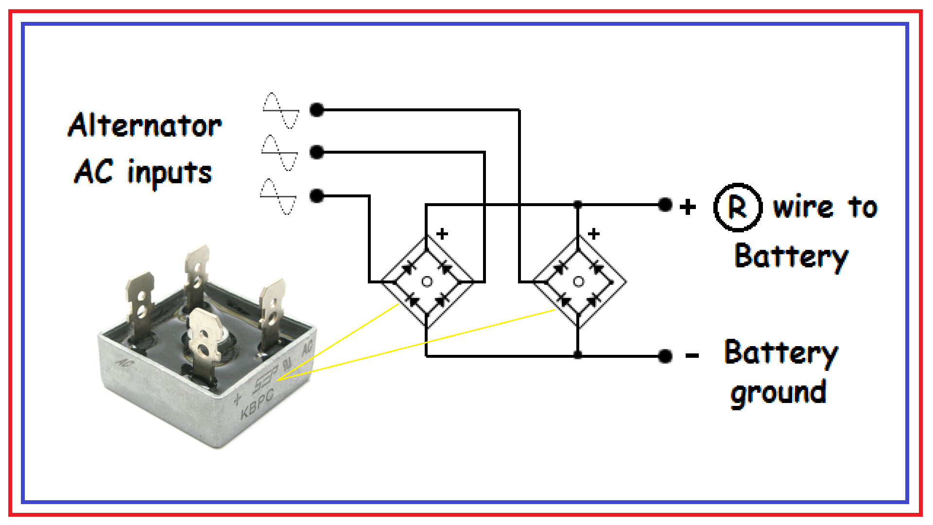
Back to the rectifier assembly only . . . .referring to the schema below:

If you have to make up a rectifier unit from scratch consider some of these Full Wave Rectifier blocks in metal cases, used for further heat sinking contact area.
If you trace the + battery connection to the pair of blocks you will see ONLY a diode cathode being encountered, which means NO flow from the battery to the alternator windings.
This is a strictly one way power flow . . .from the alternator into the battery.
We have no idea on the old rectifier construction, without dissection and reverse engineering evaluation, but they seemed to want to disconnect from the alternator.

It you have a bad old rectifier unit needing replacement . . . you might just try this possibility out . . . . they offer these FWB blocks voltage rated on up to 1000 volts . . . God forbid . . . .
and you pick their current rating at . .5-10-25-50 amps ?

Techno referencing:


y7RiIkm.png


73's de Edd


.
 
Last edited:
Looking at the post #1 pic, is the alternator 2-phase rather than 3-phase? I'm reading it this way :-
The G wire goes to the field winding (shown in the external box), whose current is controlled by module 7 which is not only an ignition module but also a voltage regulator.
There are 2 phase windings, connected by BN wires to the rectifier module.
There is a dedicated ignition winding connected by the R wire to module 7.
 
.


Sir
Jim Hood . . . . . . . . . . . . . .

I was wondering what Colin was referring to, as that is being a proper rectifier circuit for common 3 phase alternators.
But he came back with no supplication.
Then I look back to where I had initially referred on my small laptop, and now I see that you have a two phase alternator.
So your O wire would just be disconnecting the alternator common from the Rectifier block in SWITCH off position and a second section of the switch disables the sensor feed to the electronic ignition module.

BUT to be sure . .can you confirm your cycle.

WHAT I really seem to see is that you have an Eye -tally-an motorcycle that was REBADGED as a Harley.
Can you also confirm if it is a :
SX175/250 or SS-250 or called a Sprint.

In order to be sure that I will be referring to the right diagram . . . . as I have 2 Harley manuals s plus the one you referred to for wiring.


Are the units SWITCH positions:

OFF
IGNITION
IGN + LIGHTS
PARK

Does the alternator use :
GREEN
YELLOW
BROWN
BROWN
RED
BLACK
Connective wiring ?

Does the ignition module use
GREEN
RED
VIOLET
BLACK
BLACK (possibly shared with the above BLACK as 1 terminal)
Connective wiring ?

Is the existing / old rectifier a potted epoxy block Dansi brand with 5 connections

"i have a universal single phase regulator on its way. it has 2 ac inputs, power out, and ground wires."

That seems to read like it might be 1 quart short . . .3 AC connections


73's de Edd


.
 
Top