Yes, a unipolar non-latching Hall switch. Those two Honeywell ones look fine.
Re your design.
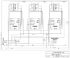
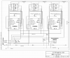
1. You can make the diagram a lot tidier if you use symbols to indicate connections to VCC and GND, you can avoid a lot of the long messy lines. Define the names of the positive and negative rails - for example, call them VDD and VSS, as is the convention with CMOS devices, or you can call them VCC and GND, or +5V and 0V. Then for pins 8 and 16 of the 4026es, and the cathode pins of the displays, just have a short wire going out and up to a net named with the positive rail, or out and down to a net named with the negative rail.
2. Each CD4026 should have its own decoupling capacitor, connected between pins 16 and 8 as directly as possible. I like to show these on the schematic right next to the IC. For example, show a wire from a VDD node (or whatever you call your positive rail) going down and then branching off into pin 16, and continuing down to a capacitor, with the bottom side of the capacitor connecting to a VSS node (or whatever you call your negative rail). That keeps everything nice and compact, and shows that the capacitor is associated with that IC. Also, the Hall sensor should have a decoupling capacitor as well. If you mount the Hall sensor off-board, with a three-wire connection, put the capacitor directly across the Hall sensor, at the end of the cable.
3. You seem to have confused the reset pushbutton with the VCC rail. It's connected between VCC and GND, and the RESET signal is tied to VCC. You need to separate that out. You're right with the 10k resistor from RESET to GND.
4. The displays won't be very bright, because the one you chose, the Lite-on LTS4301JR (
http://www.digikey.com/product-detail/en/LTS-4301JR/160-1533-5-ND/408206) has a ligh output of less than 1 mcd at 20 mA current!
As I pointed out before, the CD4026's outputs can't supply much current, especially at only 5V supply voltage. They certainly won't be able to supply 20 mA, even if you use them without current limiting resistors.
The one I suggested (
http://www.digikey.com/product-detail/en/TDSR1060/TDSR1060-ND/4074621), running at only 1 mA, will be seven times brighter than the one you chose, running at 20 mA!
If you want to reconsider your options, start with this Digi-Key filter:
http://www.digikey.com/product-search/en?FV=fff40008,fff80024,980009,10c0001,3440002,87c0011,87c0015,87c0017&ColumnSort=543&stock=1&quantity=1&pageSize=250. I recommend the first one, as I said before, or the following group of Avago ones that are rated to operate at 5 mA.
5. You need a pullup resistor on the output of your Hall sensor. Those Hall sensors (like most Hall sensors) have an "open collector output" that can pull down to 0V but does not pull up to the positive supply. In the same way that the RESET line needs a 10k pulldown resistor because the pushbutton only pulls up, not down, you need a 10k (roughly) pullup resistor between the Hall sensor's output and the positive supply rail. You don't need (and shouldn't have) the 1 MΩ resistor and the 100 nF capacitor between the Hall sensor's output and 0V.
Finally, when you export and upload line drawings, it's best to use GIF or PNG, not JPG. JPG is designed for photographs and other continuous-tone art and doesn't do very well with line drawings. If you want your lines to come out cleanly, you need to use a low compression factor, which means a large file size. PNG is the best option.
")