Sir wizard-zoso . . . . . (
E w w w w w w . . . . .( With its
W . I . Z . A . R . D aspect, being received / conceived / expressed with a definitive panaceim of fright
! )
OH ! . . .I see . . .you
Amerikanski . . . . . . . .
HOW YOU ?
Finding no relevant model
NT-520k info, am I correct in the suspicion that this is being a 13'ish inch size of screen and made in China.
Since, it doesn't research out . . . . . any too good.
You say . . .
Multipurpose LED Tester, My Leds do light up on my TV, that only has one line (2 wires). Red and black,
So, with that tester supplying its OWN internal power supply to the LED strip you tested,and lit up, that implies that there is not power coming to the LED strip from the LED power supply on the Tee Wee chassis.
My Naxa NT-520k board # is (CV3458H-A50),Passes the flashlight test
Can I interpret that . . . as that by using the indirect reflected light from the flashlight, that you are then able to make out the subdued video display on the TV screen ?
YOU GOTS A PICTOOR !
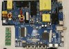
Two things I now want to point out . . . . .
Initially, start at extreme top left corner and drop down the left side until you come up on the bottom left corners cluster of a YELLOW X2
poly cap and two adjunct line choke / baluns and a reddish brown rectangular AC line fuse housing / case and a nearby round, green, line surge input thermistor .
Now my point of interest is being that white rectangular plug to its left . . . . ( it's being mounted askew . . .to board geometry ) . . . . . since that is the type of connector usually found used for connecting the back light supply wire(s) from the power source to a back light.
Particularly on the older CFL tubes and likely being a carryover to newer LED.
( Probably because the storage warehouse had so many surplus in stock at the CFL to LED conversion time.)
Now go back to the top left corner and I suspect that YELLOW transformer, being responsible for the power supply to your back light.
See if you can track your LED back light wires as ending at this specific area .
If not finding it there, I rely upon you to track down that LED supply wire to its end power source area and it should have a / some ? 100 volt'ish rated E-cap(s) very nearby for use as its DC filtering.
Additionally, around the board, I can see one open balun and two YELLOW and one black transformer that also might be candidates for that specific / separate LED supply. . . . . . . if that initial guess was incorrect.
I now turn the parts search aspect back to you.
If this is a smaller LCD screen, it usually will split up the LEDs and have strips, both, across the top and across the bottom to then have the LED's beam , edge lighting INTO the tapered clear plexiglass molded interply.
You say . . .
i bought another board but by accident i shorted something out and do not know where to look first as i do not see any glass fuses.the board supplied voltage but then the TV would turn off again,
For the sake of simplicity, first you check ALL of the power diodes and power FET's / Transistors found on the board to see if your boo-boo didn't leave any of them dead shorted, then, hopefully, you will find . . . . .
My earlier mentioned reddish brown, rectangular block fuse, has blown up into an open circuit.
In my final cursory overall examination of the board I am now running around and assuming / assigning connectors functions . . . . that is, until I get to the final end right top corner and that connector and its proximity to 2 power rectifiers and E-cap . . . . along with this possibly being a small screen unit . . . . is that possibly being a DC connector for 12V DC battery operation of this unit ?
Now, lets consult this other board shot.
SUPPLEMENTAL MAIN BOARD REFERENCING . . . . .
or
( SUPER mag . . . option . . . off site
https://i.ebayimg.com/images/g/bloAAOSwxPRgKtI4/s-l1600.jpg )
And this one sort of backfired on me, since the person took a pic that is not quite being in
good focus.
Now, of the two . . .mouse cursor click on . . . . mag options, use the smaller option . . .which is still being HUGE . . . . . as compared to your initial small pics offering.
Then use the mouse activated bottom and right side bars to slide the image across the screen.
73's de Edd . . . . .
Just remember,
that once you're over the hill,
you then rapidly begin to pick up speed.
( I can positively vouch for that ! )
.
+++++++++++++++++++++++++++++++++++++++++++++++++++++++++++++++++++++++++++++++++++++++++++++++++++++++++++++++++++

")