Sir john2k . . . . .
DAMN you
Charlie Brown . . .for having left so many variables unanswered .
Joe Blow is going to come up with 4 or so possibilities/ answers . . . . . . my brain HURTS ! as it is is coming up with 1478 answers, all in accordance to un supplied / specified variables .
Initially lets confirm if the LEDs are just . . .
ALL . . . .being constantly on power presence / illumination indicators . . .OR . . . . is one lighting up as its associated key is being depressed ?
Are the inter connecting foil paths on the other side of the keyboard visible or do we have an
UN-viewable sealed sandwich construction ?
Tell us what keys Roman I thru IV function is being . . . . . I
Open Door . . .II
Feed Dog . . . . .III
FIRE . . . . . .IV
SPELL CHECK . . .etc . . .etc . . . .
KEYBOARD REFERENCE IDENTIFICATION ASSIGNMENTS . . . . .
View attachment 55418
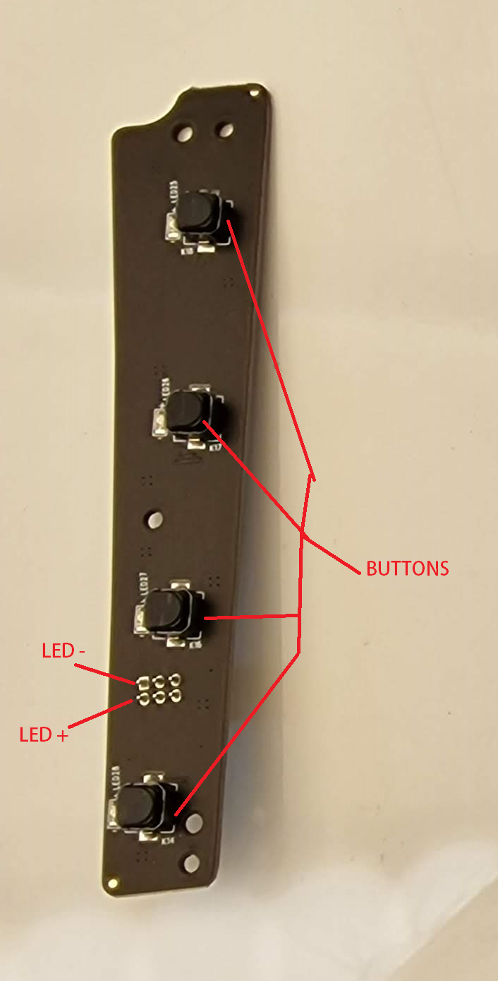
If the LEDs are just for illumination, I would expect the a and d pin connectors to terminate to 1-3-5-7 and 2-4-6-8.
If key activated we would have to "ohm out" that possibility of connections.
Sir Bertus referencing of normal pin connections being in duplicate, on the MAJORITY of tact switches, do not seem to be the case here, with only two contacts used on your switches.
Now if you pull out ohmmeter and put in lowest ohms scale and then short meter probes together to see what meter reading you then get.
That will be a direct shorted connection indication.
If you now move to the A thru H connections in OHMs metering, I would suspect direct connections being between A-C-E-G
or the other possibility of B-D-F-H connections.
Whichever combination which you do not find interconnected, leaves the other options individual contacts to be connected to b-c-e and f pin connections
Also check to meter out and see if the string of A-C-E-G or B-D-F-H connections might also directly connect to a or d.
Next tell us which of the I - IV switches needs to have function reversals on ?
It would just be a simple matter of a small gauge "wire wrap" reversing jumper from each of those switches to their respective pins on the 6 pin connectors and then breaking the original foil connect path.
UNLESS you have an earlier mentioned . . . . .un viewable / and un accessible sandwiched board.
BUT . . .I can even give you a workaround for that . . .if so being encountered.
HOWDOITBE WORKINGS ? ? ? ? . . . . .
MULTIPLEXING . . . . .
Those pin connections to those 4 monitored pins are being constantly and sequentially scanned between . . .typically, upwards to 5 times a second . . . to see if a switch has been pressed at that moment in time, the units u/Processor can then determine which switch was depressed and respond in that functions activation. accordingly.
Thaaaaaaaaaaaaaaaaaaasit
My thoughts are . . . . . . . . The farther away the future is . . . . . the better it looks.
.


