Maker Pro
Maker Pro

Measuring Sine Wave Using ADC

Hi i want to measure a sine wave of say 1.2V, 1Khz using an ADC. I am Using MAX 1204 ADC. How will i get the Digital Values correspond to 1.2V, 1 Khz Sine wave ? I successfully tested MAX 1204 using a Voltage divider feeding 1.2V input to MAX1204 . But I cant measure sine wave of 1.2V, 1Khz. !!! :(
 

KrisBlueNZ

Sadly passed away in 2015
The MAX1204 uses a three-wire SPI (serial peripheral interface) connection to a host microcontroller or microprocessor. Have a look at Figure 6 on page 13 of the data sheet. This diagram shows the signals you need to provide to the MAX1204 in order to read the data back from it, one bit at a time. SPI is a widely used protocol between microprocessors or microcontrollers and peripherals such as ADCs (and others). Tables 2, 3 and 4 on page 11 of the data sheet show you what you need to send and receive over the SPI connection to get the results of the ADC conversions. Do a web search on SPI if you need more information.
 
You could try converting to a square wave and then measure the period using the timers of the micro. Then take the reciprocal of this and you have your frequency. Otherwise I think you will need to sample a lot to measure a sine wave.
Just an idea
Adam
 
I have successfully tested MAX1204 by giving input using a voltage divider. and it is giving correct Digital Value. for example for 1.2V. the correspond Digital value is 12Ch. My question here is can we get digital value for a SINE WAVE of 1.2V amplitude
 

(*steve*)

¡sǝpodᴉʇuɐ ǝɥʇ ɹɐǝɥd
Moderator
If you're trying to measure the peak voltage then you probably need to use a peak and hold circuit otherwise you may miss the peak (it may occur between samples)
 

KrisBlueNZ

Sadly passed away in 2015
Your problem description isn't very clear but I think I've figured out what you're asking.

You can feed 1.2V DC into the MAX1204 and read that back as a converted value of 0x12C or 300 decimal, which is correct for a 10-bit ADC with a 4.096V reference, right?

So you want to acquire a 1.2V peak or 1.2V peak-to-peak sinewave? You need to superimpose the sinewave on a DC bias voltage. Normally, you bias the ADC input at half the reference voltage (2.048V), so with no signal applied, you read a constant stream of 0x1FF or 0x200 values from the ADC. When you couple the sinewave onto the input, and repeatedly tell the ADC to convert its input, you get a stream of data that represents the sinewave.

If the sinewave's amplitude is 1.2V peak, the values you read will range from (0x200 + 0x12C) = 0x32C at the positive peaks, through 0x200 at the zero crossing point, down to (0x200 - 0x12C) = 0x0D4 at the negative peaks.

You need to sample many times per cycle to get the proper sinewave shape showing through.

Does this answer your question?
 
I agree he was not very clear Kris, but he mentioned measuring a 1 KHz sine wave I guess he wants to measure the frequency also.

Adam
 
Yes, in simple i want to measure a continuously varying signal using MAX1204. say a sine wave of 1.2V peak to peak.
*"You need to superimpose the sinewave on a DC bias voltage" -> what does this mean ?
what additional changes i need to change in MAX1204 circuit to measure a sine wave ?
 

Attachments

  • MAX1204 Circuit.PNG
    MAX1204 Circuit.PNG
    31.1 KB · Views: 113
Say i am measuring a 1.2Vpp sine wave. and I want to get a continuous stream of digital values correspond to. 1.2V,1V,0.5V. The ADC may measure 1.2V at a time but next i want to get the 1V. but ADC samples say 0.75V or it may sample another random value. How can we avoid such randomness ?
 

davenn

Moderator
yup I understand that :)
not too different to what I'm doing with my digital seismograph ... I capture the full signal and display it
I use analysis software to determine peak values, frequency/period etc

are you wanting to display the captured sine wave on the computer with appropriate software ?
or are you just wanting to ( as the other guys have been trying to determine) just capture the peaks
and display a data value only ?

if just the peak values, then you need to do what Steve said in post #5

Dave
 
Last edited:

KrisBlueNZ

Sadly passed away in 2015
Yes, in simple i want to measure a continuously varying signal using MAX1204. say a sine wave of 1.2V peak to peak.
*"You need to superimpose the sinewave on a DC bias voltage" -> what does this mean ?
what additional changes i need to change in MAX1204 circuit to measure a sine wave ?
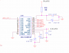
This is a simple and common way to do it:

MAX1204 Circuit annotated.png The resistors must be of equal value. They divide the reference voltage in half and set the ADC input voltage so it's centered around that voltage. So when no signal is present, the ADC should read half-scale. The resistors should be 1% or better. The signal is coupled onto the ADC input by the capacitor, which should be chosen so its reactance is very much lower than the impedance of the voltage divider at the lowest frequency of interest.

For example, common values would be 100k for each resistor, and 1 µF for the capacitor. Aiming for XC < ZDIVIDER / 10, you need to ensure that XC < 5 kΩ. This is true down to a frequency of F = 1 / (2 pi C XC)
= 1 / (2 × 3.14 × 1 × 10-6 × 5000)
= 32 Hz.

So with 2x 100 kΩ and 1 µF, frequencies down to about 32 Hz will be reproduced pretty accurately.
Say i am measuring a 1.2Vpp sine wave. and I want to get a continuous stream of digital values correspond to. 1.2V,1V,0.5V. The ADC may measure 1.2V at a time but next i want to get the 1V. but ADC samples say 0.75V or it may sample another random value. How can we avoid such randomness ?
Well, you need to sample at several times the highest frequency in the input signal. You mentioned a 1 kHz sinewave. The Nyquist frequency, which is twice the highest frequency in the input signal, i.e. 2000 samples per second for this example, is sometimes considered the minimum sampling rate that you need, but sampling at that frequency won't show you the proper shape of the waveform though. The faster you sample, the more accurately you will capture the shape of the waveform.
 

KrisBlueNZ

Sadly passed away in 2015
According to Nyquist, half of the sample rate, i.e. 66.5 kHz. But in practice, up to about 10 kHz if you want to be able to see the rough shape of the waveform.
 

davenn

Moderator
Hi Kris

I don't understand why you need the DC offset ?
is it something to do with this particular chip?

Dave
 

KrisBlueNZ

Sadly passed away in 2015
It's needed to centre the input voltage half way between the minimum and maximum voltages that the ADC can convert. This is required for every ADC that I've ever used. Perhaps there are some that convert both positive and negative voltages, and use 0V as the centre value, but the MAX1204 isn't like that.

ADCs map a range of input voltages to a range of conversion results. Taking an 8-bit ADC for simplicity, the conversion result range is 0~255. 0 corresponds to an input voltage of VREF- which is usually 0V, and 255 corresponds to an input voltage of VREF+, which is some positivie voltage from the reference voltage generator, or sometimes just the VDD voltage if you're not too concerned with accuracy.

The 0V line of the input signal has to be between those two voltages, so that both positive and negative excursions will fall within the conversion range of the ADC. So normally a bias of half of the VREF voltage is applied to the input to ensure that.
 
Hi,
I am using MAX1204 in single ended mode (V CC=5V & VSS=GND).So can i measure a sine wave by this arrangement ? also the sine wave i want to measure doesn't goes to below 0V it swings only in positive side :'(
 

davenn

Moderator
It's needed to centre the input voltage half way between the minimum and maximum voltages that the ADC can convert. This is required for every ADC that I've ever used. Perhaps there are some that convert both positive and negative voltages, and use 0V as the centre value, but the MAX1204 isn't like that.

ADCs map a range of input voltages to a range of conversion results. Taking an 8-bit ADC for simplicity, the conversion result range is 0~255. 0 corresponds to an input voltage of VREF- which is usually 0V, and 255 corresponds to an input voltage of VREF+, which is some positivie voltage from the reference voltage generator, or sometimes just the VDD voltage if you're not too concerned with accuracy.

The 0V line of the input signal has to be between those two voltages, so that both positive and negative excursions will fall within the conversion range of the ADC. So normally a bias of half of the VREF voltage is applied to the input to ensure that.

I have used several different ADC's on the seismograph projects over the last 15 yrs
none of them have I had to supply a DC offset .... hence why I asked
As you say the MAX1204 isn't one of them :)'

yeah looking at the datasheet I see the problem, a pity the OP hadn't chosen a different ADC ;)


Dave
 
Last edited:

davenn

Moderator
after digging up an old datasheet for my first digital seismo using the ADC0831.
I have to partly retract my earlier statement :oops:
The ADC0831 did not have a ± input it had a 0 - 5V input range. Looking at my circuit, I didn't have any offset in the
ADC circuit so maybe I did the offset in the datalogging software .... was a long while ago haha

Dave
 
Top