Maker Pro
Maker Pro

Measuring negative current

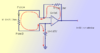
I have one doubt in the below circuit, the circuit is for measuring the current
upload_2021-5-31_20-59-19.png
I have not put in all the components, but the gain of the opamp is around 15. When the current is 0 i read at the output of the micro 1.65V.
When the current is flowing from Point A to Point B the voltage at the micro is greater than 1.65 and less than 3.3V. It is called the positive current?
When the current is still flowing from point A to Point B the voltage at the micro is less than 1.65V and above 0V. It is called the negative current?
Is the understanding correct? My main question is either the current is positive or negative the flow is from Point A to Point B? How is it possible? For negative current it should flow from Point B to Point A? Please advise.
 
The golden rule to remember here is - if the supply voltage for the opamp and it's output allow:
  • There will be an equal amount of current through both resistors (you should label them for reference). Therefore ohms law applies.
  • The negative input of the opamp wil have a voltage nearly equal to positive input.
  • Be aware of where the current actually flow (see my drawings with arrows). Note that current path are incomplete due to Vcc/Vee is not included in drawing.
Also, the gain of the opamp didn't sound correct. Are you referring to voltage or current gain for a very rare opamp model? Gain of an opamp should be so high that it normally isn't taken into account in equations for this kind of use.
 

Attachments

  • opamp-drawing.png
    opamp-drawing.png
    29 KB · Views: 5

Harald Kapp

Moderator
Moderator
I have not put in all the components, but the gain of the opamp is around 15.
Please do provide all components. The circuit as shown will not have a gain of 15. We need to see the complete circuit (at least the part around the opamp) to be able to see what you are actually doing and tell you whether it is correct or not.

When the current is flowing from Point A to Point B the voltage at the micro is greater than 1.65 and less than 3.3V. It is called the positive current?
No. A positive current from A to B will create a positive voltage drop between A (positive) and B. This voltage is fed to the inverting input of the opamp, thus reducing the output voltage, not increasing it

My main question is either the current is positive or negative the flow is from Point A to Point B? How is it possible? For negative current it should flow from Point B to Point A?
It is not clear from your drawing where the current comes from (incomplete schematic). Also as shown by @Kabelsalat there will be current provided by the output f the opamp via the feedback resistor which will add to the current through the sense resistor. Am I right to assume you want to build a kind of current sensor? Then an inverting opamp is a bad choice for the amplifier due to its low input impedance. Read e.g. this application note on current sensing for more information.
But I digress from the original question. Whether the current through the sense resistor is positive or negative can be determined from the voltage drop between points A and B. If current flows from A to B and the voltage between A 8+) and B(-) is positive, then the current is positive, too. If the voltage between A nd B is negative, the current is negaitve, too. This is easily explained by Ohm's law:
V = R × I
With R being the (positive) resistance, it follows that the polarity of the voltage equals the polarity of the current. Since you have point B fixed at 1.65 V, you could be able to measure positive currents as well as negative currents, provided you replace the amplifier by an opamp circuit suitable for this design (see the link above or look up "opamp current sensor circuit" on the internet).
 
Top