Maker Pro
Maker Pro

Magnifying light voltages

I have one of these magnifying lights on my desk which has packed up.

Electronics1.jpg

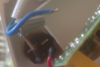
There is a 4pin plug which connects the round fluorescent tube. I am in South Africa 230VAC mains 50Hz. The 4pin plug has two grey wires and two brown wires. What voltages should I be seeing on those pins? And will I only be able to see those voltages when the fluorescent strikes.

Hmm. Just wondering if I'm flogging a dead horse. Shove some leds in there as a replacement?
 
Fluorescents take a couple of thousand volts to "strike" and you won't be able to measure it anyhow.
Best just to check the pins on the lamp itself.
If they are intact(circuit on each pair) then the driver is kaput.
 

bertus

Moderator
Hello,

On the tube you should measure two times low resistance for the filaments.
It will be between a gray and brown each time.

Bertus
 
Thanks Bertus - between gray and brown = valuable information In the region of 5Ω?That's what I'm reading between the gray/blue sets.
So that means I have a problem on the board itself. Busy tracing out the design, might help
 
Measured voltages on the 2 x MJE13003 Bipolar NPN transistors. All voltages in relation to neg of big cap.
Q2= 135/313/136V
Q1= 0/135/0V
 
Have you checked the diodes on the base on the transistors?.
Also there is DB3? Next to Q2. Biderectional diode? Tranzorb?.
Anyhow, I get approx 22Ω both ways on the diodes in circuit. The DB is 0 both ways in circuit.
I’ll check voltages against yours later, but your second measurements don’t sound right.

Martin
 
Quite amusing update.
Just took my circuit board out and plugged it in. It’s not working now!.
I’ll have to get my 2nd one out to check this one now.

That DB3 may well be a TVS.

Edit- My neutral wire fell out. There are lots of dry joints too. I will re-flow them all.
Martin
 
Last edited:
Hi Martin
How much for your crystal ball? I had to pull the diode to see the DB3
Agree with your 0 both ways on DB3 Diode. Diode on the other side beeps like a short with a reading of 13 both ways. (could be a zener?)
 

bertus

Moderator
Hello,

The MJE13003 is a NPN high voltage power tranistor.

Bertus
 

Attachments

  • MJE13003_MOSPEC.pdf
    182.7 KB · Views: 3
Well, I got some measurements albeit with an auto DMM. Quite different to yours.
315V across C2 10μF 400V.

With negative from cap, as you did,
Q1
B 315V and also shorts the lamp out.
C 310V
E 210V
Q2
B 0
C 190Ω
E 172Ω.
Don’t forget the only meter I have with me is auto ranging DMM. So I got no voltage at Q2.
If you can, put your meter to auto?. If not, it’ll be Tuesday when I’m home.

Martin
 
Hi Martin

Note:
1. Running PCB through dim bulb
2. No fluorescent bulb attached
3. No autoranging meter

Agree 315V across C2

Agree voltages look quite strange:
Code:
              Q1                                               Q2
      Martin    Dries                                  Martin   Dries
B     315        136                                     0        0
C     310        315                                             137
E     210        137                                              0
Ohms at Q2
B 18Ω
C OL
E 5Ω

My reading of 136V at B of Q1 does not short the lamp

Can we agree that the pinouts of MJE13003 are as shown below?
mje13003-pinout.jpg


Moderators note : used code tags to preserve spaces
 
Last edited by a moderator:
Yes, pinout the same.
An auto DMM is not ideal for this. Going across circuits, the poor thing wont know whether I want Ohms, mA, volts or resistance.

No dim bulb tester here. I’ll try knock one up today.
In fact, my son is coming here today so we can change the oil in his car. I’ll give him a small list to bring with him. A DMM and lamp limiter.

I’ll disconnect the tube also as my measurements were with it connected.
What is “Martin Dries?

Martin
 
Top