Maker Pro
Maker Pro

LC parallel tank circuit

Hi all,
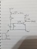
I have seen a common emitter transistor circuit with a LC parallel tank circuit connected between the base and OV.
I want to ask why this would be the case and how to test it.

If I found the resonance point by sweeping frequencies on the LC circuit (i think it is around 140KHz), should the current be at a maximum and voltage at a minimum?

Is that a good way to test the circuit?
Thanks in advance.
 
When the L/C circuit is in resonance, its impedance will be very high. This means that it will allow signals at its resonant frequency into the base circuit of the transistor whilst attenuating those above and below.
 
Thank you very much for your help.
Can I ask a good way to test the circuit? If I inject a signal say sine wave 1V pk to pk at the resonant frequency or sweep it, will at resonance I will see a sine wave at collector output and either side a lower amplitude sine wave?
 
The simple way to check the resonant frequency of your L/C circuit is to disconnect it from the transistor circuit. Connect a 1K resistor to one end of it so that they are in series and then connect a sine wave signal generator across the resultant circuit. Connect an oscilloscope across the L/C circuit and then whilst monitoring with the scope, sweep the sig' gen' frequency. You will notice that the sig' gen' trace will rise and fall with frequency. When the voltage across the L/C circuit is at a maximum, your circuit is in resonance. Make a note of the frequency.
 
The simple way to check the resonant frequency of your L/C circuit is to disconnect it from the transistor circuit. Connect a 1K resistor to one end of it so that they are in series and then connect a sine wave signal generator across the resultant circuit. Connect an oscilloscope across the L/C circuit and then whilst monitoring with the scope, sweep the sig' gen' frequency. You will notice that the sig' gen' trace will rise and fall with frequency. When the voltage across the L/C circuit is at a maximum, your circuit is in resonance. Make a note of the frequency.
Thanks. How could I check with the transistor in the circuit?
 
The schematic shows 0 volts on the emitter of the npn transistor. I would think that the emitter to be ground.
Inject the signal between the base of the pnp transistor and ground The output from the collector of the npn
transistor will be higher at resonance and drop off as the frequency is increased or decreased.
 
The simple way to check the resonant frequency of your L/C circuit is to disconnect it from the transistor circuit. Connect a 1K resistor to one end of it so that they are in series and then connect a sine wave signal generator across the resultant circuit. Connect an oscilloscope across the L/C circuit and then whilst monitoring with the scope, sweep the sig' gen' frequency. You will notice that the sig' gen' trace will rise and fall with frequency. When the voltage across the L/C circuit is at a maximum, your circuit is in resonance. Make a note of the frequency.
Hi,
Would i be able to bring a LC circuit with a resonance that is same as the schematic to produce a mutually coupled circuit?
I think this may let the signal pass to the collector (which is fed into a micro gpio pin), i am not sure but i think the pnp is then switched on (driven by the gpio pin) and this supplies 3V to the LC circuit. Does that seem logical. I cant understand what the pnp is doing other than to supply 3V to the LC circuit, but why should it need to do this?
Thanks in advance
 
Must confess, I don't know what the circuit is for.
I think it is part of a mutually coupled circuit, at a particular frequency, the coupling with this and another circuit will interact.
I believe that it detects proximity to another circuit and when the resonant frequencies match, they start to communicate.
 
Hi all,
Please can someone show me how to verify that the current is low, impedance is high and voltage is low for a parallel lc tank circuit.
Also how can i verify this using pspice.
Thanks
 
The simple way to check the resonant frequency of your L/C circuit is to disconnect it from the transistor circuit. Connect a 1K resistor to one end of it so that they are in series and then connect a sine wave signal generator across the resultant circuit. Connect an oscilloscope across the L/C circuit and then whilst monitoring with the scope, sweep the sig' gen' frequency. You will notice that the sig' gen' trace will rise and fall with frequency. When the voltage across the L/C circuit is at a maximum, your circuit is in resonance. Make a note of the frequency.
Hi
Should the voltage be at a max for resonance? The current minimum and impedance maximum. Is there anyway I can verify this by calculation?
Thanks
 

Harald Kapp

Moderator
Moderator
1) measure current and voltage.
2) make the simulation, use SPICE probes to "measure" current and voltage.
Calculate impedance from current and voltage. Note that you need to take the phase relationship into account, therefore measuring these values requires amplitude and phase (e.g. by oscilloscope).
 
First of all. The voltage across A very simple way you resonant circuit will be at a maximum when it is at its resonant frequency.
A simple way to arrive at them is to calculate the L and C values by assuming that their impedances are 50Ω each. Do the sums with the known factors ie Z (Impedance) and f (Frequency). I will leave to search google on how to do that. It is pretty straight forward.
Hi
Thanks, I will post what I have done in Pspice, LC in parallel with a resistor to the parallel connection all connected across a 1V pkpk Sinewave. I have added a voltage probe across the LC part and see a dip in the voltage at a resonant freq of around 189KHz. The inductor is 7mH and the cap is 100pF.
I would expect a peak from what you mentioned but see the opposite.
I will upload a few screen shots.
Best regards
Raj
 
Top