Maker Pro
Maker Pro

JFET Voltage Controlled Switch

Hi all,

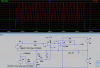
So, not surprisingly, I'm having voltage control problems again. This time, I want to use a JFET (or any transistor, really) as a voltage-controlled SPST switch. I've read college papers, articles, and blog posts about it, but all I end up getting when I try it is obscure/bias/source voltages, inversions, or no change at all between the input and output.

I know I'm a noob and I'm probably just screwing things up, but does anyone know of a sure-fire way to do this? What I find really embarassing is that I once wrote an article on making an analogue bitcrusher which used a JFET-based voltage-controlled switch, and I can't even get that to work anymore (it did at the time).

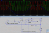
If you are curious as to why I need this, I want to use it for routing audio. I have a couple ideas, such as sequentially selecting outputs from my multi-waveform oscillator, and routing audio within a filter for interesting multi-timbral effects.

As an example, here's a small list of the places I've been trying to figure this out:
http://www.allaboutcircuits.com/vol_3/chpt_5/2.html
http://answers.yahoo.com/question/index?qid=20080127204831AAIynpw
http://www.circuitstoday.com/wp-content/uploads/2009/08/jfet-as-analog-switch.jpg
http://en.wikipedia.org/wiki/JFET
http://www.geofex.com/Article_Folders/bosstech.pdf
http://ist-socrates.berkeley.edu/~phylabs/bsc/PDFFiles/bsc5.pdf
http://www.premierguitar.com/Magazine/Issue/2007/Jun/JFET_Switching.aspx
http://stinkfoot.se/archives/503
http://sub.allaboutcircuits.com/images/quiz/02094x01.png
http://www-g.eng.cam.ac.uk/mmg/teaching/linearcircuits/jfet.html

Thank you for your help.
 
Ordinarily I would feed audio through a 10k resistor and switch by shorting the output end of the resistor with a mosfet such as a SD210. The gate should be driven by 0 to 5 volts and I would integrate the gate signal with a resistor and a capacitor so as not to drive the gate too fast as this would add a noticeable "click" in the audio.

You can look at hands-free telephone circuits or intercom circuits.
This is probably the easiest and cleanest way of doing it.
 
Thanks! If I had a MOSFET at all I would know for sure, but in simulation that seems to have the same problem a lot of designs I've tried have: the output is the same no matter the gate voltage. I tried that with a JFET on a breadboard with the same problem. Works in theory, at least, just not in practise. Thanks though.

I'll look into them, thanks!
 
I'm frustrated. I think I need to know your exact application.
Audio switches are used in many places such as in CD players and DVD players. Schematics are readily available in the internet. Maybe you are not biasing them right. Have you considered using a SD5000 quad switch?
 
Generally, I just want a voltage-controlled SPST. That's really it. Sure, I'll be routing audio (and maybe transient voltages) with it, but it will act just like a normal switch.

I have considered IC switches, but it just seems like since transistors are known for their use as switches this would be a piece of cake. I already have dozens of transistors sitting around, no reason to go out and buy a special IC for something I should be able to do with what I have, you know what I mean?
 

KrisBlueNZ

Sadly passed away in 2015
One thing to beware of, when using MOSFETs like this, is the body diode. It's in parallel with the MOSFET between drain and source, and obviously, it's still present when the MOSFET is turned OFF. So when the MOSFET is OFF, it is open-circuit in one direction, but in the other direction, it's only an open circuit for voltages below about half a volt!
 

KrisBlueNZ

Sadly passed away in 2015
I've used JFETs for audio switching and had no problems. Can you post some schematics? There may be an error we can spot.
 
Sure thing!
http://img802.imageshack.us/img802/4923/jfet.png
I've tried these, variations on these (switching CV polarity and switching source and drain), and using BJTs in the same instances. All do nothing. I've also tried a couple more complex designs which ended in complete failure - those are linked to above. (Edit: oh, uh, on the upper right drawing, reverse the diode. Not sure why it's like that...)

However, out of all this I have learned one thing which I needed: how to use a JFET as a resistor. Only problem is it's rather difficult to control...
 

KrisBlueNZ

Sadly passed away in 2015
I mean a complete circuit. There's no way to know what the DC voltages on any of the JFET terminals would be when you just draw an abstract diagram like that.

Can you draw a complete circuit with an AC-coupled audio input and output and a clear indication of the ON and OFF voltages of the control voltage.

With an N-channel JFET the gate should never be driven more positive than the source or drain. Driving it more than a few volts negative with respect to the source or drain turns the JFET OFF.
 
I would, except the uses change drastically, as do the input voltages. Maximum is 8V p-p (so +-4V), minimum probably around 0V, signal waveforms are different... I'd literally have to draw about 40 or more different drawings to get all possible aspects - doable, but I doubt either of us wants to go through that. This is why I need/want "a sure-fire way to do this".

I learned about that when making a JFET act as a resistor. That's why I feel the bottom-left drawing would do the trick: lower resistance to ground would short the signal, higher resistance would make it continue normally. But, in practise, this is not such.
 

KrisBlueNZ

Sadly passed away in 2015
How about posting the full diagrams for two different connections that both don't work. That will give us a starting point.
 
Sure thing! Sorry, I should have thought to do that.
http://img837.imageshack.us/img837/4610/36959596.png
The top image is most of a filtering module (it's not missing anything important, don't worry). The switching system changes the output filter type: bandpass or highpass. OpAmps are powered, +-9V. Currently, this circuit has absolutely no effect.

The bottom image is simply an OpAmp oscillator. The switch would make the output be on or off. Currently, this circuit simply offsets the oscillations +1V.

Thank you again.
 

KrisBlueNZ

Sadly passed away in 2015
OK. I've been playing with LTSpice to test out some ideas too. Its JFET model doesn't seem to be very accurate, and seems to have quite a high Rds(on). I'd be interetsed to know which real-life device they have based it on. But I don't have any models of real-life devices to compare with, or to use when testing. :-(

Re your diagrams. The top one seems to be a single-pole low-pass filter followed by a single-pole high-pass filter, using non-inverting amplifiers with gain adjustable using switches and potentiometers. The input to the high-pass filter can be selected as either the main circuit input, or the output of the low-pass filter. Is that what you want? I also noticed R6 which isn't needed in that circuit and won't have any effect.

Both JFET gates are biased at -2V. This will probably be somewhere in their linear region (depending on the details of the JFET model). If you want the JFET to switch OFF, you really need to bias it at -5V or more.

The bottom diagram is a square-wave oscillator built around a Schmitt trigger implemented with an op-amp. You can't connect the JFET straight across the output of the op-amp; its ON-resistance isn't low enough to counter the drive current from the op-amp. You need to connect a resistor between the op-amp output and the JFET drain, and take the output signal from the JFET drain. A value of 1K~10K will do. It depends on how much attenuation you want when the JFET is ON. In this case I would use a digital gate rather than a JFET.

I've been doing some experimenting with LTSpice. My first thought is that if there's any appreciable signal on the source or drain of the JFET, this can affect the JFET's switching behaviour. Remember that the JFET's bias is determined by the gate-source and gate-drain voltages, not the absolute voltage on the gate; voltage variations (due to signal) on the source and drain will appear (to the JFET) to be gate-source and gate-drain voltage changes, which will affect its bias and therefore its resistance, if they happen to fall within the range that the JFET responds to.

So I figured one way to eliminate the signal voltage on one side of the JFET, at least, would be to use it in an inverting amplifier stage, with its source connected to the inverting input of the op-amp, which is a "virtual ground" point because of the action of the op-amp and the feedback loop. That's all well and good, but when the JFET is OFF, its drain voltage still varies, and this causes the problem that you can see in the first screen capture.

attachment.php


This circuit uses J1 to pass (or not pass) a 1 kHz sinewave from V3 into inverting amplifier U1. J1's source is held at 0V. The circuit is powered from +/- 9V and signals are referenced to the 0V rail.

J1's gate is driven with the signal shown in blue, which I have deliberately given a long rise and fall time. The red trace is the circuit's output, and the green trace is the signal at J1's drain (the left side).

You can see that when the control signal (gate voltage) is at 0V or at -9V the output is correct. A control voltage of 0V allows the signal to flow through J1, and a control voltage of -9V biases J1 fully OFF and no signal appears at the circuit's output.

The problem is when the control voltage is slightly below 0V. The output shows half-cycles of signal, which occur when the drain voltage gets within about 1V of the gate voltage, and the JFET starts to conduct because the gate-drain voltage is not negative enough. (A JFET is actually pretty much symmetrical, so the gate has to be negative with respect to both the source AND the drain in order to bias the JFET OFF.)

I've done some web searching but found no answer to this problem. In fact the circuits I've found actually have audio on BOTH ends of the JFET. They use a diode between the control voltage and the gate, but that won't help with this problem.

So if they can ignore this issue, I will too. As long as the control voltage changes fairly quickly, it won't be noticeable.

So the next capture shows a circuit with a digital control input. The control signal is relative to the -9V rail, and it turns the transistor ON and OFF. The transistor's collector voltage swings between 0V and -9V, and this voltage is filtered by a simple R-C network so that the gate voltage doesn't change too suddenly, which would cause an audible pop at the output of the amplifier because of the gate-source capacitance, which would couple the rapid voltage change into the amplifier itself.

attachment.php


This circuit's performance looks a lot better. You can see the control signal from pulse generator V4 on the graph, as well as the JFET's gate voltage, which doesn't move sharply, so no glitches are visible on the output signal.

That's where I'm up to with my experimentation and research. There are a few other ideas that have arisen though.

If you don't need extremely fast response, an LED visually coupled to an LDR is a good way to switch signals. If you need a large amount of attenuation, putting one LDR in series with the signal followed by a second one from the signal to ground, and driving the two LDRs with opposite signals, will do that. The same idea can be used with any attenuator if you need a lot of attenuation.

The CD4016 or CD4066 can be used for audio switching, but I think you'll have a problem with clicks, because they aren't designed to switch gradually through a linear region. If you happen to switch the signal off when the signal voltage is near a peak, there will be a sudden sharp edge at the output, which will sound like a loud bang or click.

I've seen a suggestion for using the CD4007 as a mute. It's an unusual CMOS device that consists of several separate MOSFETs. Google analog switch CD4007 for more.

Another approach is to use a voltage-controlled amplifier (VCA) controlled by a voltage that is slew-rate-limited by a simple RC (or shaped in some other way). This will give a nice clean smooth transition between 0 dB attenuation and some large attenuation (80 dB or more).

Finally, many manufacturers make analogue switches of various kinds. You could start by searching Digikey for "analog switch" and download some data sheets.

What do you think?
 

Attachments

  • yoa01-1.gif
    yoa01-1.gif
    21.3 KB · Views: 1,578
  • yoa01-2.gif
    yoa01-2.gif
    18.4 KB · Views: 990
Yeah, I never use LTSpice for accurate modeling. I can't find any accurate models online and don't know SPICE, either. I'm using (currently) MPF102's from Radioshack, but should have more this week from Futurlec.

Well, it's not what I want, but your description is accurate. Those filter models are merely stand-ins for voltage-controlled 12dB resonant filters I will install. R6 and R13 are not required? Well, saves room, at least. Thanks. I was thinking about biasing it more, but I wasn't sure how much.

Depending on the resistance I can get out of my JFETs, I could probably attenuate it enough so that I could get it nearly silent, right? I'm trying to keep it all analogue. I'd rather use a 4066 than a digital solution.

In the paragraph above capture two, do you mean digital as in an analogue signal with but two states (which I've heard that's all digital is), or an actual digital signal?

LED+LDR=vactrol, right? If so, then I've considered that, but given both speed and how it is incredibly hard to find LDRs or vactrols, it doesn't seem like a good solution. I've tried using Vactrols for voltage control before, but though they are easy and make VC very simple, it's hard to use that for everything unless I can find a good source. Believe me, if I can find a bunch of vactrols of varying resistances I'd be set!

I've heard of people using RC lowpass filters on a 4066's control voltage input to reduce clicking, would that work?

I still need to figure out how to make a VCA as well. My problem with that is I only know of two ways to do it: an attenuator, or adjusting an OpAmp's gain (or, of course, some crazy-huge circuit which makes no sense to me). Though, I just thought of the last one a few days ago and have not thoroughly tested it.

Well, firstly I think you like SERIOUSLY know electronics. I understand everything you said, but would have never thought to put together those circuits. You have my utmost respect. Second, I think if I could figure out a good way to make a VCA that would be doubly useful because VCAs are used everywhere in my line of electronics (synthesizers and other audio electronics). I think I should be able to figure that out well enough given my library of schematics and the DIY team over at Muff Wiggler. I also like the idea of IC switches, but was hoping to avoid them. Seems like it would be the best solution, though.

So I guess now it's back to my electronics workbench and to some testing! I can't thank you enough, Kris.
 

KrisBlueNZ

Sadly passed away in 2015
Depending on the resistance I can get out of my JFETs, I could probably attenuate it enough so that I could get it nearly silent, right?

Yes, I think so.

I'm trying to keep it all analogue. I'd rather use a 4066 than a digital solution.

Technically the 4066 _is_ digital - at least, it's part of the CMOS 4000 series, which are digital ICs. But I know what you mean.

In the paragraph above capture two, do you mean digital as in an analogue signal with but two states (which I've heard that's all digital is), or an actual digital signal?

The former. If your signal has only two states, you can amplitude-modulate it by feeding the signal into a transistor in common emitter configuration, with its collector load resistor connected to a voltage that's present (e.g. +9V) when you want the signal, and not present (0V) when you don't.

That causes a DC swing (a shift of the average DC voltage of the signal) when the signal is turned ON and OFF, so perhaps a more complicated circuit would be better, but the circuit doesn't have to be linear if it's just operating in two states. That was my point.

LED+LDR=vactrol, right?
Yes, I've heard them called that.
If so, then I've considered that, but given both speed and how it is incredibly hard to find LDRs or vactrols, it doesn't seem like a good solution. I've tried using Vactrols for voltage control before, but though they are easy and make VC very simple, it's hard to use that for everything unless I can find a good source. Believe me, if I can find a bunch of vactrols of varying resistances I'd be set!

I didn't realise they were becoming hard to find. I guess there's not much demand for them. Digikey have 38 hits in the category "Sensors, Transducers > Photo Detectors - CdS Photoconductive Cells (Ambient Light)" but they're only from two different manufacturers. Mouser only have one product listed. That's a shame because if you don't have the need for speed, they're pretty convenient.

I've heard of people using RC lowpass filters on a 4066's control voltage input to reduce clicking, would that work?

I've suggested it myself, but I've never tried it, and I haven't heard back from the guy I suggested it to. I kind of doubt it actually, but why don't you try it, and let me know how you get on? Make a note of the manufacturer and exact part number you test with.

I still need to figure out how to make a VCA as well. My problem with that is I only know of two ways to do it: an attenuator, or adjusting an OpAmp's gain (or, of course, some crazy-huge circuit which makes no sense to me). Though, I just thought of the last one a few days ago and have not thoroughly tested it.

A while ago I tried to help another user with gating and VCAs in another thread: https://www.electronicspoint.com/4047-4066-audio-slicer-help-t254416.html

Well, firstly I think you like SERIOUSLY know electronics. I understand everything you said, but would have never thought to put together those circuits. You have my utmost respect.
Thanks :) Like everyone here I have my strengths and weaknesses.
Second, I think if I could figure out a good way to make a VCA that would be doubly useful because VCAs are used everywhere in my line of electronics (synthesizers and other audio electronics).
I believe the LM13700 is widely used for general VCA applications. It's what I suggested in that other thread I linked to.
I think I should be able to figure that out well enough given my library of schematics and the DIY team over at Muff Wiggler.
Who are they? That sounds like a euphemism... I'd better not ask!
I also like the idea of IC switches, but was hoping to avoid them. Seems like it would be the best solution, though. So I guess now it's back to my electronics workbench and to some testing! I can't thank you enough, Kris.
You're welcome! Good luck, and anything useful you find, please post it here.
 
I know that Doepfer (Eurorack-format modular synthesizer pioneers) uses vactrols in some of their modules, but I would have no idea what vactrols they use without looking at the board. They have pics on their site, but you can't see anything of use.
http://www.doepfer.de/A100_pictures/doepfer_a-101-9.jpg
http://www.doepfer.de/A100_pictures/doepfer_a-101-2.jpg
But, I did see some guy's blog and saw he was using a VLT5C4 vactrol. I'll keep searching. Would it be easier to make my own vactrols? I mean, it's hard to find LDRs, but maybe I could find something. I don't necessarily need speed, but I also don't want such a slow responce that everything acts like old Buchas, which used Vactrols for a lot of VC elements.

Time to grab some 4066's. For science!! Here's to hoping Mouser takes PayPal.

I just got a small shipment from TI of 13700s, and after seeing the datasheet it seems you can build pretty much ever aspect of a synthesizer with these things.

Yeah, it does sound dirty, but they are the world's largest modular synthesizer forum. Here's the DIY section: http://www.muffwiggler.com/forum/viewforum.php?f=17&sid=e815591668996317b73d51db01f67620

I will. Just requires time, as does everything.
 
Maybe 13700s will replace CEMs, eh? haha!

Holy crap LDRs cost a lot. Eh, well, as previously stated... FOR SCIENCE! At least I can get like 100 LEDs for dirt cheap.
 
Top