Hello,
My name is Tom, I am doing a project (high school- final project) that includes using an Arduino and some sensors - One of them is an Accelerometer. The project is about Parkinson's disease - I want to detect and monitor tremors with the Accelerometer....
I bought two products (both SparkFun) - LIS331 & MMA8452Q.
The LIS331 is working fine with a code that I found (which ill add).
The MMA8452Q isn't working - I hooked it up and found some codes but it never showed any values.
So I have several requests and questions
1. I used the following code for the LIS331:
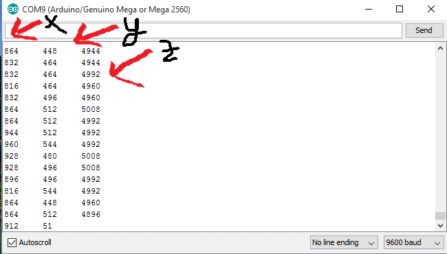
I understand how the code works but I honestly have no ideas what the values/output represents....
I read the Datasheet (https://www.sparkfun.com/datasheets/Sensors/Accelerometer/LIS331HH.pdf), section 2.5.1 about sensitivity - I tried to understand what the values represent but I just didn't understand it . what is "Gain"?
okay so I tried measuring the "sensitivity" (I still have no idea what it means). I pointed the Z axis straight down:
It shows -6000 (approximately) when I point the Z axis straight down......
This is the axis indicator:

This is how I pointed it:

*the picture is rotated but the Z axis points downwords
so it means that 6000 = 1g?
It doesn't sound right.....
-----------------------------------------------------------------------------------------------------------------------------------------------------------------
2. I tried hooking up the MMA4852Q with the hooking up guide of sprakfun -
https://learn.sparkfun.com/tutorial...up-guide?_ga=1.26243133.1813833853.1450790034
And it just showed nothing :

This is how I hooked it up:


*If you are wondering - I used two pairs of resistors (220 & 100 Ω each) because I didn't have 330 Ω resistors.
Am I doing something wrong? because I am pretty hopeless......
My post might be too long...I'm sorry
and if something is wrong with my post (not according to the forum rules or something) - please say and ill change it!
Thanks in advance for everyone,
Tom
My name is Tom, I am doing a project (high school- final project) that includes using an Arduino and some sensors - One of them is an Accelerometer. The project is about Parkinson's disease - I want to detect and monitor tremors with the Accelerometer....
I bought two products (both SparkFun) - LIS331 & MMA8452Q.
The LIS331 is working fine with a code that I found (which ill add).
The MMA8452Q isn't working
- I hooked it up and found some codes but it never showed any values.So I have several requests and questions
1. I used the following code for the LIS331:
Code:
#include <LIS331.h>
#include <Wire.h>

LIS331 lis;
int val;

void setup() {
  Serial.begin(9600);
  lis.begin();
}
void loop() {
  val = lis.getXValue();
  Serial.print(val);
  Serial.print("\t");
  val = lis.getYValue();
  Serial.print(val);
  Serial.print("\t");
  val = lis.getZValue();
  Serial.print(val);
  Serial.println();
}
I understand how the code works but I honestly have no ideas what the values/output represents....
I read the Datasheet (https://www.sparkfun.com/datasheets/Sensors/Accelerometer/LIS331HH.pdf), section 2.5.1 about sensitivity - I tried to understand what the values represent but I just didn't understand it . what is "Gain"?
okay so I tried measuring the "sensitivity" (I still have no idea what it means). I pointed the Z axis straight down:
It shows -6000 (approximately) when I point the Z axis straight down......
This is the axis indicator:
This is how I pointed it:
*the picture is rotated but the Z axis points downwords
so it means that 6000 = 1g?
It doesn't sound right.....
-----------------------------------------------------------------------------------------------------------------------------------------------------------------
2. I tried hooking up the MMA4852Q with the hooking up guide of sprakfun -
https://learn.sparkfun.com/tutorial...up-guide?_ga=1.26243133.1813833853.1450790034
Code:
/******************************************************************************
MMA8452Q_Basic.ino
SFE_MMA8452Q Library Basic Example Sketch
Jim Lindblom @ SparkFun Electronics
Original Creation Date: June 3, 2014
https://github.com/sparkfun/MMA8452_Accelerometer

This sketch uses the SFE_MMA8452Q library to initialize the
accelerometer, and stream values from it.

Hardware hookup:
  Arduino --------------- MMA8452Q Breakout
    3.3V  ---------------     3.3V
    GND   ---------------     GND
  SDA (A4) --\/330 Ohm\/--    SDA
  SCL (A5) --\/330 Ohm\/--    SCL

The MMA8452Q is a 3.3V max sensor, so you'll need to do some
level-shifting between the Arduino and the breakout. Series
resistors on the SDA and SCL lines should do the trick.

Development environment specifics:
    IDE: Arduino 1.0.5
    Hardware Platform: Arduino Uno

This code is beerware; if you see me (or any other SparkFun employee) at the
local, and you've found our code helpful, please buy us a round!

Distributed as-is; no warranty is given.
******************************************************************************/
#include <Wire.h> // Must include Wire library for I2C
#include <SFE_MMA8452Q.h> // Includes the SFE_MMA8452Q library

// Begin using the library by creating an instance of the MMA8452Q
//  class. We'll call it "accel". That's what we'll reference from
//  here on out.
MMA8452Q accel;

// The setup function simply starts serial and initializes the
//  accelerometer.
void setup()
{
  Serial.begin(9600);
  Serial.println("MMA8452Q Test Code!");
  // Choose your adventure! There are a few options when it comes
  // to initializing the MMA8452Q:
  //  1. Default init. This will set the accelerometer up
  //     with a full-scale range of +/-2g, and an output data rate
  //     of 800 Hz (fastest).
  accel.init();
  //  2. Initialize with FULL-SCALE setting. You can set the scale
  //     using either SCALE_2G, SCALE_4G, or SCALE_8G as the value.
  //     That'll set the scale to +/-2g, 4g, or 8g respectively.
  //accel.init(SCALE_4G); // Uncomment this out if you'd like
  //  3. Initialize with FULL-SCALE and DATA RATE setting. If you
  //     want control over how fast your accelerometer produces
  //     data use one of the following options in the second param:
  //     ODR_800, ODR_400, ODR_200, ODR_100, ODR_50, ODR_12,
  //     ODR_6, or ODR_1.
  //     Sets to 800, 400, 200, 100, 50, 12.5, 6.25, or 1.56 Hz.
  //accel.init(SCALE_8G, ODR_6);
}

// The loop function will simply check for new data from the
//  accelerometer and print it out if it's available.
void loop()
{
  // Use the accel.available() function to wait for new data
  //  from the accelerometer.
  if (accel.available())
  {
    // First, use accel.read() to read the new variables:
    accel.read();

    // accel.read() will update two sets of variables.
    // * int's x, y, and z will store the signed 12-bit values
    //   read out of the accelerometer.
    // * floats cx, cy, and cz will store the calculated
    //   acceleration from those 12-bit values. These variables
    //   are in units of g's.
    // Check the two function declarations below for an example
    // of how to use these variables.
    printCalculatedAccels();
    //printAccels(); // Uncomment to print digital readings

    // The library also supports the portrait/landscape detection
    //  of the MMA8452Q. Check out this function declaration for
    //  an example of how to use that.
    printOrientation();

    Serial.println(); // Print new line every time.
  }
}

// The function demonstrates how to use the accel.x, accel.y and
//  accel.z variables.
// Before using these variables you must call the accel.read()
//  function!
void printAccels()
{
  Serial.print(accel.x, 3);
  Serial.print("\t");
  Serial.print(accel.y, 3);
  Serial.print("\t");
  Serial.print(accel.z, 3);
  Serial.print("\t");
}

// This function demonstrates how to use the accel.cx, accel.cy,
//  and accel.cz variables.
// Before using these variables you must call the accel.read()
//  function!
void printCalculatedAccels()
{
  Serial.print(accel.cx, 3);
  Serial.print("\t");
  Serial.print(accel.cy, 3);
  Serial.print("\t");
  Serial.print(accel.cz, 3);
  Serial.print("\t");
}

// This function demonstrates how to use the accel.readPL()
// function, which reads the portrait/landscape status of the
// sensor.
void printOrientation()
{
  // accel.readPL() will return a byte containing information
  // about the orientation of the sensor. It will be either
  // PORTRAIT_U, PORTRAIT_D, LANDSCAPE_R, LANDSCAPE_L, or
  // LOCKOUT.
  byte pl = accel.readPL();
  switch (pl)
  {
  case PORTRAIT_U:
    Serial.print("Portrait Up");
    break;
  case PORTRAIT_D:
    Serial.print("Portrait Down");
    break;
  case LANDSCAPE_R:
    Serial.print("Landscape Right");
    break;
  case LANDSCAPE_L:
    Serial.print("Landscape Left");
    break;
  case LOCKOUT:
    Serial.print("Flat");
    break;
  }
}
And it just showed nothing :
This is how I hooked it up:
*If you are wondering - I used two pairs of resistors (220 & 100 Ω each) because I didn't have 330 Ω resistors.
Am I doing something wrong? because I am pretty hopeless......
My post might be too long...I'm sorry
and if something is wrong with my post (not according to the forum rules or something) - please say and ill change it!
Thanks in advance for everyone,
Tom
