Maker Pro
Maker Pro

Help with bend sensor circuit

Hi all,

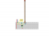
What I'm attempting to do is use a bend sensor from Spectra Symbol to provide an output of 0-5v. I've pored over the various diagrams, looking mostly at this:

bend_sensor_post.jpg


which outlines how to use an op amp to provide a 0 - 5v swing in the output. I measure 11K to 22K fully bent.

Here's my problem. I've wired and rewired that circuit on a breadboard and cannot get it to function properly. My questions for the forum are this;

1. How do i provide a negative 5v Vref? Do I need another part in front of the op amp? It seems pretty important to be able to provide a negative Vref...
2. The Op Amps I have are TS272s, LT1168s, LT1101 and a quad Op Amp, are any of these what I need? Do I need a rail to rail op amp?
3. Do i need to provide the Op Amp with power? In each of the various diagrams I've only seen the inverting, non inverting and output connected, never Vcc or anything else.
4. Really this is my first official Op Amp circuit so I I'd appreciate any additional advise.

I'm open to getting any additional parts but I'd like to be able to solve this quandary. This will be for a gestural interface project using an Eobody 1: http://www.mesi.fr/page_produits.php?prod=16
 
1.: See 3.
2.: See 3.
3.: Yes. I guess the need for a power supply is so obvious that it usually "goes without saying". If you use a +/- 5V supply then you need a rail-to-rail opamp.
4.: There's always a first, no prob's. I never heard about a bend sensor before..
 
1.: See 3.
2.: See 3.
3.: Yes. I guess the need for a power supply is so obvious that it usually "goes without saying". If you use a +/- 5V supply then you need a rail-to-rail opamp.
4.: There's always a first, no prob's. I never heard about a bend sensor before..

Okay, i guess to clarify, the Eobody unit outputs 5v, I have the end of the bend sensor connected to the 5v then according to the diagram I posted, the non inverting input connects to ground and there is a resistor that connects the inverting input to the output which connects to the signal wire on the input to the Eobody. What I'm having a hard time figuring out is if i need to connect the Vcc and ground on any of these Op Amps (primarily the TS272 as the Linear ones seem to be instrument amplifiers with more going on than just normal op amps). to the same power being delivered from the Eobody output. If I do need to connect the Op amp, how do I connect it in such a way that then I provide a -5v for Vref as it states in the diagram.....

Thanks
 
Like I said, all op-amp's needs power, and this circuit needs a negative power rail as well as a positive. Does the EoBody provide only +5V? If so you need some extras/changes.
 

Attachments

  • Bend_sensor_to_eobody_bb.png
    Bend_sensor_to_eobody_bb.png
    77 KB · Views: 312
Like I said, all op-amp's needs power, and this circuit needs a negative power rail as well as a positive. Does the EoBody provide only +5V? If so you need some extras/changes.


Thanks for the help Resqueline, the Eobody provides only +5v AFAIK, to be honest I reckoned that I was missing something in the circuit diagram but couldn't figure out what.

So even though the example diagram (in my first post) doesn't indicate the Op amp needs additional connections to +5v and 0v, there are some assumed connections? This is what I am missing. Here's a link to ITP Sensor Workshop on bend sensors, 3/4 of the way down the page they explain the issue that I think you are trying to illustrate.

Resistance to Voltage Converter - use the sensor as the input of a resistance to voltage converter using a dual sided supply op-amp. A negative reference voltage will give a positive output. Should be used in situations when you want output at a low degree of bending.

So I need a dual supply op amp, with a -5v, +5V and 0v connections? Is that possible with my TS272? I guess I'm still a bit stumped on how to provide -5v if and when I need to.

Again, thanks for the help. very much appreciated
 
Your first diagram is a principal diagram, with no pinouts or other parts spec's. (except resistor values). You're expected to have a base knowledge.
You'll need to Google and try to make yourself familiar with datasheets - and preferably Application Notes too. Both of these contain loads of learning potential.
Yes, the TS272 has the same pinout as the one used in your breadboard picture. It's the PSU that's "dual supply", not the op-amp - they don't have a 0V connection.
To make a negative supply from a single positive you can use a device like the ICL7660. It comes in the same package as the op-amps and just need a capacitor.
An inverting amplifier configuration like you have there, being "hinged" around 0V needs a negative supply due to Kirchoff's laws of current (& voltage). Google that.
There may be other ways to reach the 0-5V output requirement and not having to have a negative supply.
One could imaging "hinging" the amplifier around 2.5V instead, but then the signal will be 2.5-5V and therefore needs to be level-shifted down 2.5V and amplified by 2.
This however may become more complex and costly than just adding a negative supply.
 
Requeline,

thank you, you are a godsend. or a flying spaghetti monster send.

I am just assembling a NE555 chip via this link:

1.gif


To provide a -5v voltage.

From there I connect my +5v to Vcc+ and my -5v (or whatever the negative output of the 555 is) to the Vcc- on the Op amp...Then wire the -5v to the Vref connection for the bend sensor voltage divider circuit?

again thanks a million,

jah pastafari
 
flex_sensor_v1_schem.png


Is where I stand currently. I get .810V reading from the 0v lead out of the Eobody and Output 1 pin of the TS272. I've got something screwy here I just cant tell what.
 
Last edited:
Good find on the 555. It looks like it would work. But you say you get .81V on the 0V? Referenced to what? The 0V should be your reference, and should therefore be 0V.
If 0V isn't 0V everywhere then you need to inspect the (ground) wiring integrity. Also, measure +5V, -5V, and some of the DC & AC voltages on the various 555 pins.
You can also try to disconnect power from the op-amp & the 555 in turn, and see if the power supply voltages bounce back up where they should be.
 
I've decided to do it right and go for the ICL7660 as I'm looking to make the footprint as small as possible. I was able to get -2.5 from the 555 in the end using this Instructable http://www.instructables.com/id/How-to-Make-a-Voltage-Inverter/ but I think my on hand capacitor selection may have prevented me with achieving -5v. Ideally this will go into an Arduino instead of the eobody as the Eobody outputs MIDI and I'm needing something that will output OSC...

Thanks again for the help Requeline...
 
Top