Maker Pro
Maker Pro

Help wiring in 6A dial into Western Electric 302 rotary telephone

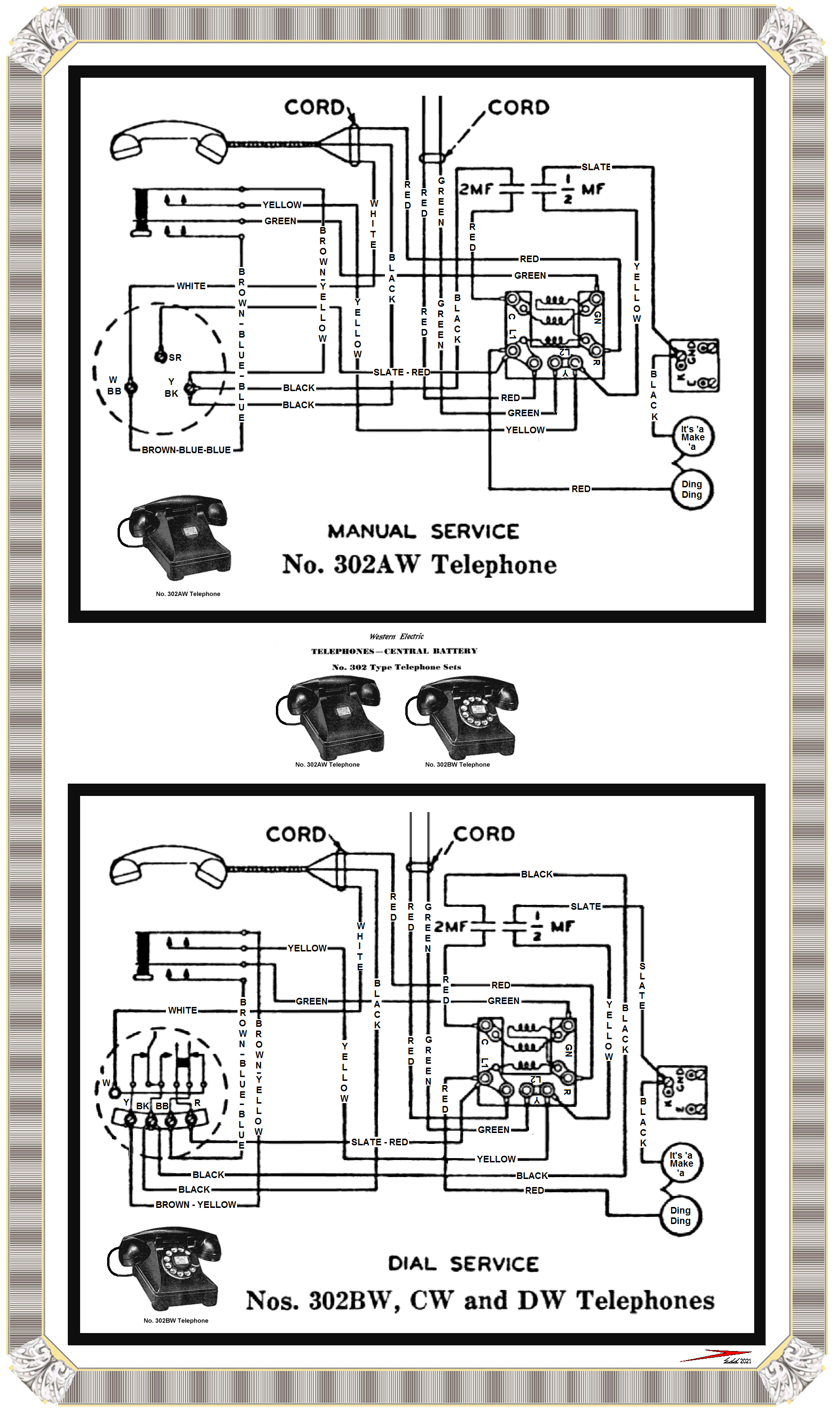
I have a Western Electric 302 phone that was originally an old hotel phone, so it didn't have a dial - just the blank with the room number, etc. I purchased a 6a Northern Electric dial and have been trying to get it wired in correctly. The problem I have is unique enough that I have not been able to find help with it, even from the company I purchased the dial from.

Here's the problem: The dial is wired in and the phone rings and I can even dial a number and it connects, but the only time I can hear a dial tone or the person on the other end is if I pull down on the dial just a little bit like I'm starting to dial. If I let go of the dial, I hear nothing, but the person I'm talking to can still hear me ok.. The call disconnects when I hang up the receiver.

I have gone over the wiring diagrams so many times and visited numerous websites and viewed hours of youtube videos, and I just can't figure out why the receiver is working exactly opposite as it should when the dial is installed. If I take out the dial and wire the blank (the piece with the room number, etc on it) back in, I can receive calls and can hear a dial tone and hear the person on the other end just fine.

What am I missing with the wiring of the dial? Or is it wiring from the handset to the body of the phone?
 
Maybe you have it wired correctly but the dial is out of calibration.
When the dial is back to its resting position, it may overshoot by a fraction.
Check the mechanism for anything slightly bent.
I have never played with one and am guessing by your description so apologies if it’s BS.

Martin
 
Sir gelpaks . . . . . (And thats being gelpaks . . .ehhhhhhh . . . not six packs . . .? )

I submit two relevant wiring diagrams, that I have reworked from their 1948'ish vintage lettering . . . . thereby enhancing its wiring color coding identifications / readability.

LOOKING AT ITS USE IN ITS ORIGINAL MANUAL MODE . . . . .

When you used the phone it in its bare bones / manual hookup, the insert panel for the then non existent dialer was just serving as a physical and electrical wiring terminus for its 6 incoming terminal leads on its 3 screw terminals .

REFERENCING THE FIRST / TOP ILLUSTRATION . . . . .

Doing a relevant sections run down, at top center we have the phone line coming in and routing down to the L1 - L2 terminal block and its associated audio mixing / coupling transformers
At the top are two paper capacitors for providing DC isolation, the right one being a one half ufd for AC coupling the pulsating ring tone to drive the bell and the left 2 ufd one for audio coupling.
The ringer bell is at bottom right corner.
Left bottom corner is the insert panel and its 3 terminal screws.
Above it is the handset cradle switch for the handset just above it.

REFERENCING THE SECOND / BOTTOM INTER WIRING ILLUSTRATION . . . . .

Top center is the phone line coming in and routing down to the L1-L2 terminal block and its associated audio mixing / coupling transformer.
At the top are two paper capacitors for providing DC isolation, the right one being a one half ufd for AC coupling the pulsating ring tone to drive the bell and the left 2 ufd one for audio coupling.
The ringer bell is at bottom right corner.
Now the left bottom is having a 6A dialer installed with its 4 + 1 terminals which accommodate 6 connections.
Note that there are two sets of leaf switches associated with it, the 4 leaves on the right which are responsible for muting your ear piece of the hand set during dial pulses so that you do not get LOUD POP-POP-POP's in your ear when dialing.
And there is the far left single leaf switch set, that creates your individual dial pulses.
Note its long right leaf with an offset hook to it.
As you start dialing your number, you will run clockwise thru a specific rotary distance until your finger reaches an initially mandated dial stop point.
When the dial is then released, a geared down mechanical escapement imparts an evenly timed rotation back to the dials finger stop / initial start point.
This rotary escapement mechanism is also activating an eccentric cam that is pressing against that offset leaf switch and it disrupts switch contact and creates a dial pulse for each switch disruption made.
Up above is the handset cradle switch, and the handset at the top.

With your finding that the unit will work fine with the manual hook up.
But, then when you wire in a dialer, your mentioned . . . .slight . . . initial movement of the dial and its degree of correction, suggests that you check out all of the wiring to the dial connections.
That's particularly from the dialers 1+4 screw terminals and THEN their short wire runs up / over to the leaf switch contacts. Could two wires have been transposed ?

If aged wiring is making it difficult to positively read and confirm color coding, just trace that wire on back to its connection origin . . . . . then it's being compared to this supplied schematic..

Thaaaaaaaassit . . . . .

ITS IN THE BOOK . . . . . . AND HERE ARE THOSE TWO PAGES . . . . .
Western-Electric-302-Phone-Wiring.png


73's de Edd . . . . .


animated-telephone-image-0081.gif


.
 
Last edited:
Top