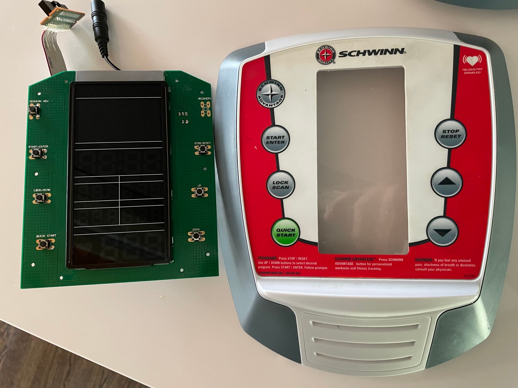
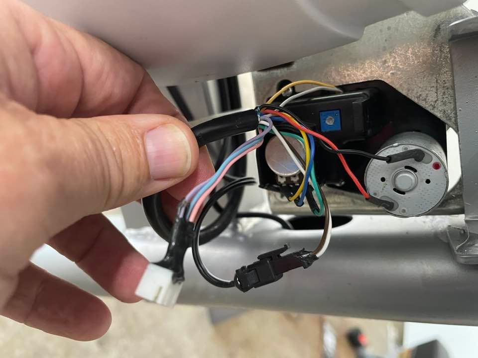
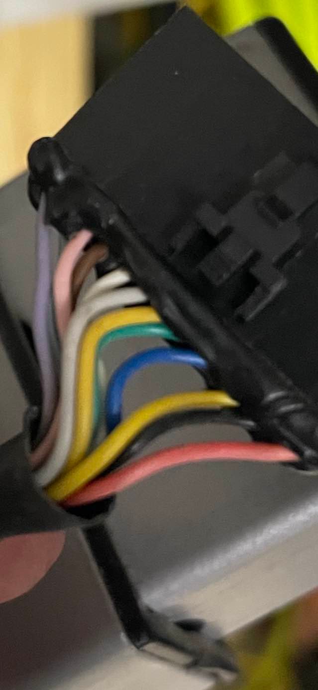
On older exercise machines, a "H Bridge" circuit is used to control the motor/magnet position for the resistance setting. See this excellent video tutorial on a teardown and fix of a failed transistor that caused the resistance circuit to fail:
However, on more modern exercisers, it does not appear that the "H bridge" configuration found above is present. Perhaps over time this "H bridge" circuit has been consolidated into a single IC? For example, this instructable illustrates the same issue as above, failed resistance circuit at the console board:
https://www.instructables.com/Fix-your-NordicTrack-Exercise-Bike/
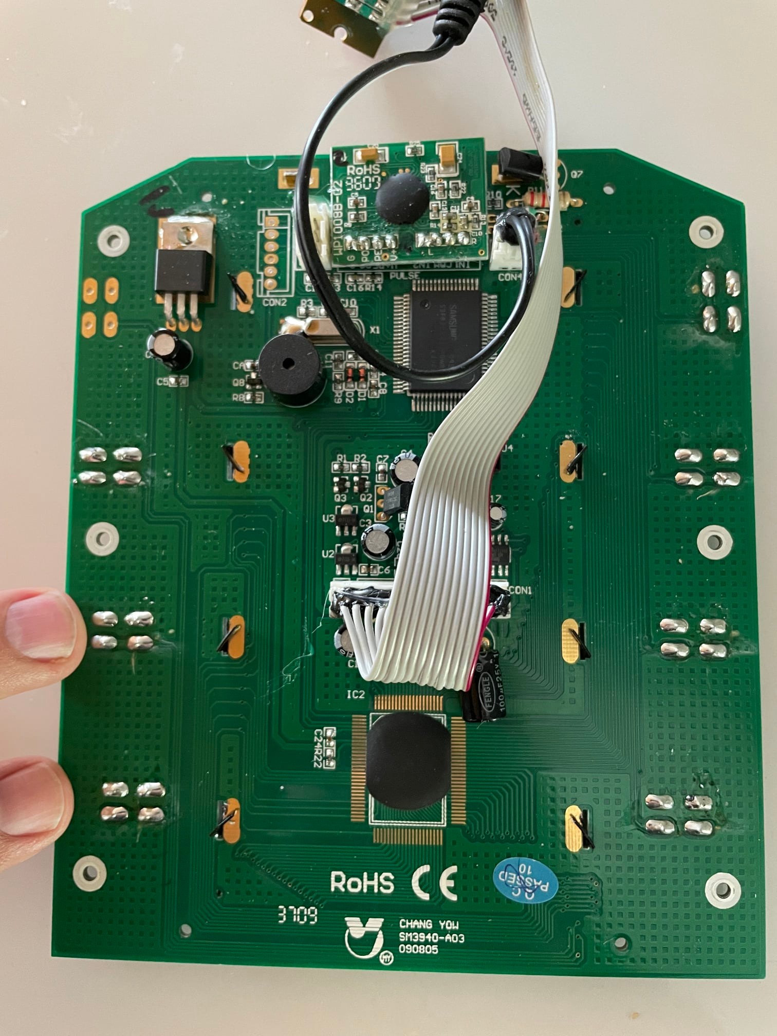
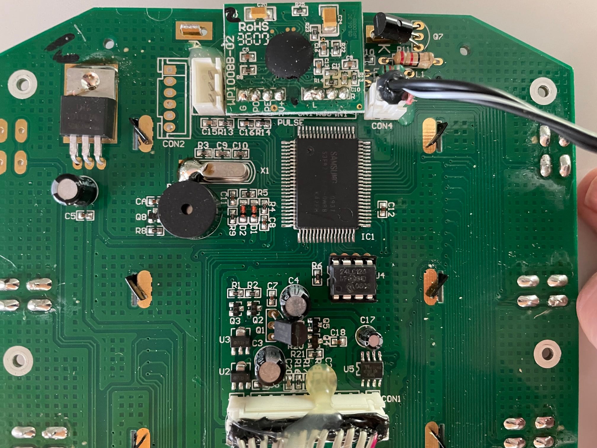
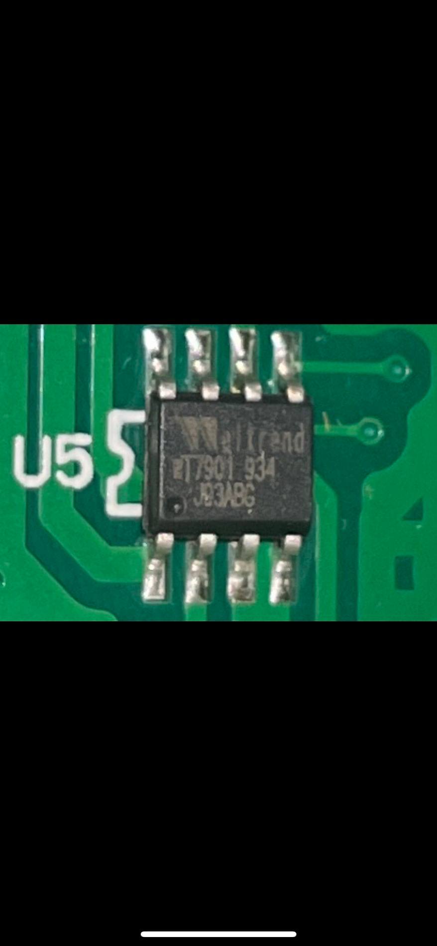
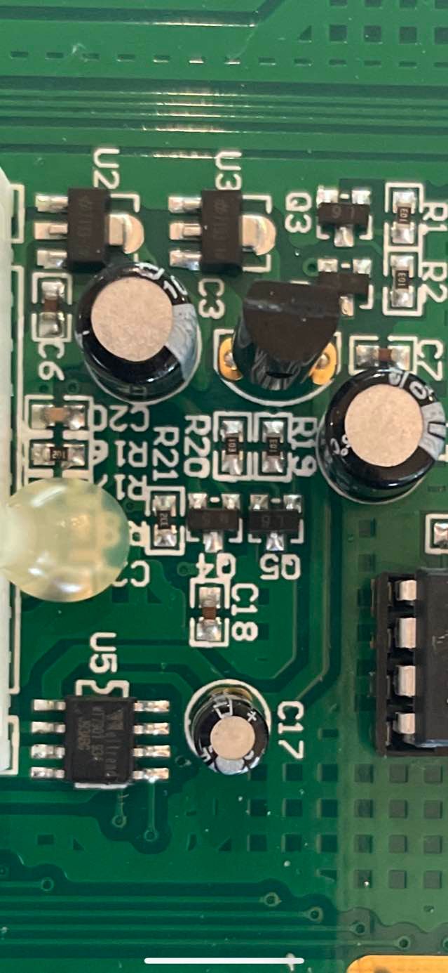
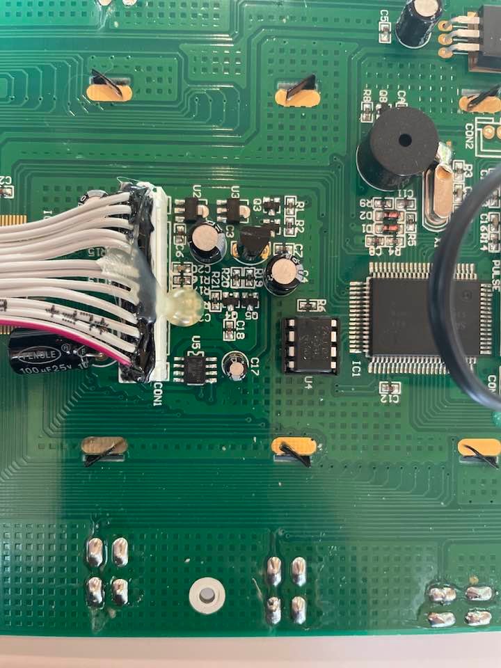
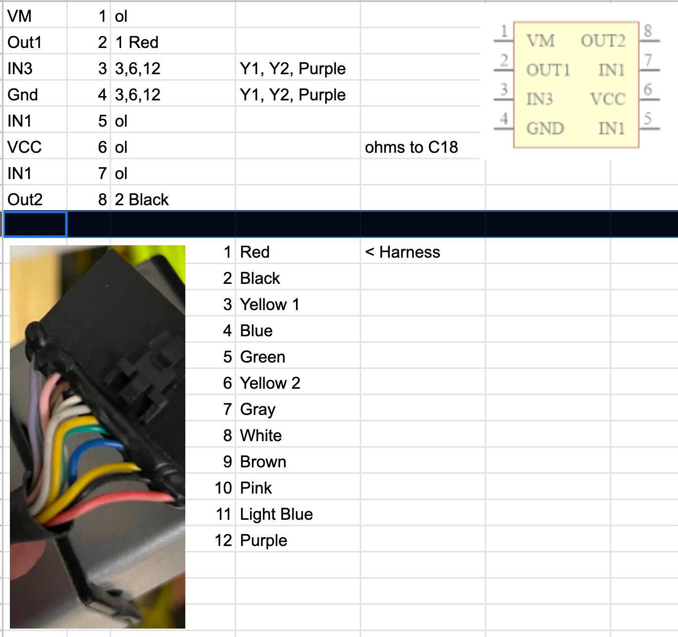
As you can see looking at the board, there does not appear to be an "H bridge" on the board (that I can see). Does it appear that a single IC chip has replaced this circuit? If so, I'm seeking to ID that chip in order to fix several consoles I have on hand that appear to have this same issue.
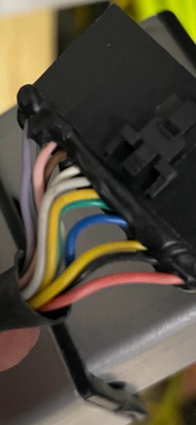
Here is another good video that illustrates how the circuit works along with expected voltages back and forth from the console circuit to the tension/servo motor and potentiometer:
