Maker Pro
Maker Pro

Electrotechnic exercise (help)

Hello everyone,
I took an exam last week and there was an exercise (look at picture) which I have no idea how to solve it.
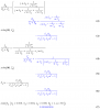
The text reports that the current generator is: j(t)=J_M sin(wt+alpha) and that the value reported by the rms voltmeter is 0. I have to find the value of the impedance Z.

I had an idea and i tried to solve it that way, but i got to nothing... I assumed that, becouse of the rms voltmeter, on C4 there is no current and then i applied the mesh current method...
Please help me i'm litterally desperate

photo_2018-09-20_16-12-18.jpg
 
First consider how one might simplify the problem. The voltmeter has infinite impedance so C4 is not relevant. The voltmeter reads zero and a zero signal has no phase, so the phase of the current source is not relevant. But the current source does cause a voltage drop from Point-A to Point-B regardless of the value of R1 & C1. So just focus on the voltage from Point-A to Point-B and you should see a bridge circuit with the voltmeter across the center of the bridge. There are two complex voltage dividers that split the A-B voltage drop and put the same magnitude & phase signal on each side of the voltmeter. Anyway, that's how I see the problem.
 
First consider how one might simplify the problem. The voltmeter has infinite impedance so C4 is not relevant. The voltmeter reads zero and a zero signal has no phase, so the phase of the current source is not relevant. But the current source does cause a voltage drop from Point-A to Point-B regardless of the value of R1 & C1. So just focus on the voltage from Point-A to Point-B and you should see a bridge circuit with the voltmeter across the center of the bridge. There are two complex voltage dividers that split the A-B voltage drop and put the same magnitude & phase signal on each side of the voltmeter. Anyway, that's how I see the problem.
thanks for your reply! Talking with some of my colleagues we thought about the voltmeter thing... first of all we are trying to understand what actually means to put that instrument there. I'm not sure but on DF we have no current and, becouse of the voltmeter measurement we have that the D node and the F node have the same potential. am i right?
 
In post #1 you said that you applied the mesh current method. What result did you get from that?
It was inconcludent... Even if you simplify the circuit you get to identities... You'll always have one missing equation becouse you need to work on the DF "wire". Since the said wire is like an open side (becouse of the voltmeter) there is no actual current flowing. And yet (again becouse of the informations given about voltmeter measure) the D and F node have same voltage. Therefore if you apply the mesh method you have to use this information, but at this point it's just better to sort things out without any recursive method. it's just easier once you understand what actually the presence of the voltmeter implies. :)
 
it's just easier once you understand what actually the presence of the voltmeter implies.
But suppose that there was no voltmeter connected; yet the problem asked you to find the unknown Z such that nodes D & F were at the same potential. So what does the presence of the voltmeter actually imply?
 
You say that this is from an exam you took last week, so it's not homework and it should be ok to provide a solution.

Laplace has already pointed out that the phase of the current doesn't matter. Furthermore, R1 and C1 don't matter either since they are in series with a current source. The current source injects 5 amps into node B and sinks 5 amps from node A. You could say that it injects -5 amps into node A.

I see a natural way to use nodal analysis to solve this network. Choosing the bottom of the diagram as the reference node and numbering the 3 other essential nodes we get this:

NetworkFindZ.jpg

Using Mathematica to solve the network, I get this result (Mathematica uses a special symbol to represent sqrt[-1]):

NetworkFZ1.png

NetworkFZ2.png

The voltage at node 2 is essentially zero; those values are just left over round off error.

Could this possibly be correct? Since the exam was a week ago, has the instructor given the result since then?
 
This problem has been setup to ensure that a solution will be found by just searching for a real (not complex) value of Z that will give a v(2) of zero.

To rule out the possibility that some complex impedance for Z would also give v(2) of zero, one can plot the voltage V(2) as a surface in the complex plane as Z is allowed to take on complex values. This means that Z might have an inductive or capacitive part and not just be pure real.

Here are two plots of the magnitude of v(2) as Z's real part ranges from -30 to +30 and its imaginary part ranges from -30 to +30.

In this plot, we're looking down on the magnitude of v(2) surface:

NetworkFZ3.png

There appears to be only place where the magnitude of v(2) goes to zero.

In this next plot we're looking underneath the surface and again we see only one place where the magnitude of v(2) drops to zero. Apparently the value our search found for Z which makes v(2) go to zero is the only solution.

NetworkFZ4.png
 
But suppose that there was no voltmeter connected; yet the problem asked you to find the unknown Z such that nodes D & F were at the same potential. So what does the presence of the voltmeter actually imply?
The voltmeter there implies that there's no current on the D-F wire i think... Since an ideal voltmeter can be seen like an open wire...
 
You say that this is from an exam you took last week, so it's not homework and it should be ok to provide a solution.

Laplace has already pointed out that the phase of the current doesn't matter. Furthermore, R1 and C1 don't matter either since they are in series with a current source. The current source injects 5 amps into node B and sinks 5 amps from node A. You could say that it injects -5 amps into node A.

I see a natural way to use nodal analysis to solve this network. Choosing the bottom of the diagram as the reference node and numbering the 3 other essential nodes we get this:

View attachment 43068

Using Mathematica to solve the network, I get this result (Mathematica uses a special symbol to represent sqrt[-1]):

View attachment 43069

View attachment 43070

The voltage at node 2 is essentially zero; those values are just left over round off error.

Could this possibly be correct? Since the exam was a week ago, has the instructor given the result since then?
The revision of the exam with the professor is set for the 25th, i'll tell you if the results are right by then... Honesltly I didn't get perfectly how you solved the exercise since i never seen your method, yet if it's right, results must be the same...
 
I didn't realize that this was a take-home exam. I thought you had already taken it as an exam in class, so I shouldn't have given you a complete solution right away. Sorry. However, you have shown some work so I don't feel too bad! :)

You have made a mistake somewhere in your work. Here's another solution that doesn't use any fancy network solving methods--just plain old Ohm's law. Eliminate R1 and C1.

NetworkFZ5.png
 
I've had a look at your work. It's difficult to follow because some of the subscripts are blurry, but the main problem I see is your calculation of Iz. You got a numerical value, but how can that be when you don't know the value of Z yet? Also, it looks like you're using the current divider rule, but you haven't used it correctly if that's what it is.
 

(*steve*)

¡sǝpodᴉʇuɐ ǝɥʇ ɹɐǝɥd
Moderator
I didn't realize that this was a take-home exam. I thought you had already taken it as an exam in class,

And hence the rules about not giving answers.

It seems you've just been fooled into doing this person's homework.

This sort of thing makes me want to identify the school the person attends and give them a heads-up about unethical student behaviour.
 
And hence the rules about not giving answers.

It seems you've just been fooled into doing this person's homework.

This sort of thing makes me want to identify the school the person attends and give them a heads-up about unethical student behaviour.

First thing he said in the first post was "I took an exam last week.", but English is not his native tongue. Maybe he meant to say "I took home an exam last week." :(

I had the impression that the exam was over, he hadn't done well on this problem, and was looking for some followup to improve his understanding. My bad.

I did note that the OP had posted some work he has done, and it comes close to being right, so I don't think this guy is a total flake.
 
Last edited:
Looking back at the last thing he said in post #1, "Please help me i'm litterally desperate", that should have been a clue to me that this was a take-home exam. :(
 
I did note that the OP had posted some work he has done, and it comes close to being right, so I don't think this guy is a total flake.
I think the OP has the right numerical answer (although I'm having trouble following how he got it.) I did the simple voltage divider approach, but since it should not matter from which direction the voltage division is done, I did it both ways (Eqns 2 & 4) to ensure the answer was the same both ways. MAPLE worksheet attached.
 

Attachments

  • Screenshot from 2018-09-23 18-25-21.png
    Screenshot from 2018-09-23 18-25-21.png
    14.5 KB · Views: 18
Top