Maker Pro
Maker Pro

Hall effect ignition

Thanks Whonoes, will study the site.

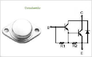
It was pointed out that the IGBT has an inbuilt hold down resistor plus some zeners therefore I don't think I need the external resistor as described above. I'm waiting on some capacitors to arrive before assembling the prototype.
Now the puzzle is how do I mount the PCB ensuring that..
1/. the IGBT has sufficient heat sink
2/. the unit is fasten-able by screws allowing air gap adjustment to the rotor-cam.
 
Looking at the datasheet for the IGBT it shows a maximum saturated state collector emitter voltage of 1.75 volts. assuming that you are going to charge the coil to 3 or 4 amps that would give a power dissipation of between 5 and 7 watts. Also they sell a surface mount version of the same chip so I question if a heat sink would be necessary.
Don't trust me though as I'm really good at letting the magic smoke out ;)
 
The surface mount chip sounds really interesting. Will study that avenue, perhaps for a future revision.

Here's where I'm at with the circuit. I've had it working but twice it ends when it blows the Geartooth /hall effect sensor. They are $10 a pop so I'm hoping to learn how to fix it. One thought is the coil flyback EMF is toasting the hall sensor. Isn't the .1uf cap supposed to help?. What's the way forward? Thanks.
upload_2017-12-28_22-30-10.png
 
It is possible that charge is being transferred to the gate via collector gate capacitance. A way to quench this would be to insert a resistor in series with the gate and then either a 12V zener diode from gate to ground or a high speed diode with anode to gate and cathode to 12V. Also there may be an issue with your wiring layout. As some fairly substantial fields will be generated, you must keep a good distance between any parts of the high voltage circuit and the control end ie hall effect device.
 
I agree that layout is important. Some time ago I looked at an electric fence energiser which used capacitor discharge to drive a high voltage transformer. The charger consisted of one board with another plugged into it at right angles. The electrons decided that this was too far round and took a short cut at the plug-in junction, producing lots of ozone which destroyed some plastic components. It was repaired using wood and loops of wire by-passing the plug and socket. It is still running years later.
I complained to the manufactures agent about the design and was told that it was correct but I never saw another one with a plug and socket.

I suggest that you make the high voltage and high currents to run in as small and smooth loops as possible to minimise magnetic and electric fields.
 
Thanks for the great ideas. Really good food for thought. Firstly I'll redraw the circuit, hopefully I can get that done tonight.
 
GTS-ignition.png

WHONOES, you make some good points. In this latest iteration I mounted the hall in the distributor while the IGBT was 2 feet away, next to the coil.
You will notice upthread, I'd scribbled out the wire to ground along with its' 10k resistor. I'd found the circuit would not work with this.
Of note is the Lobe Sensor pickups marketed by Pertronix. These are a single potted pickup inside the distributor. Proximity of hall and IGBT doesn't appear to be a factor in that case. I had emailed them but they weren't forthcoming with any suggestion re a suitable pickup for adaption to my motorcycle. They didn't even bother replying. Of course any one of their Lobe Sensor pickups might actually work for me, for all I know.
https://www.ebay.com/itm/Pertronix-...ash=item3d1edcb40b:g:m7kAAOSwhOVXerJy&vxp=mtr

Re the 0.1uf cap. I'd managed to find some of these which were 35V. Subsequently I've seen a circuit which uses a 630V model. Is my 35V 0.1uf cap not spec'd enough?

Ok, I've redrawn the circuit using a bit of 'artistic license'. I couldn't find certain symbols so I had to improvise.
Notes:
The coil is twin outlet wasted spark 5 ohm. The 2 spark plugs don't actually need a ground as shown. They only need be in contact with each other. In other words, the 2 leads, 2 plugs and part of the upper engine form their own circuit.

Just this minute I remembered, suppressor leads may help. All the testing has been without suppressor leads and non-resistor spark plugs. Are these essential?? Did they cause the early demise of the hall?

Thanks.GTS-ignition.png
 
The ground connections for the IGBT and Sensor must go to the same point using very short wires, these in turn must be as thick as you can make them. Also, do not use single strand wire, the more strands the better. Do not take the ground return for the coil to the same point.
Capacitor C1 is too small for the job in hand. The supply for the sensor could do with decoupling from the 12V supply. Do this by connecting a small value resistor 10ohms or so in series with the supply connecting it as close to the sensor as possible. Then connect a large value electrolytic capacitor of at least 100uF or more rated at 50V or over plus your original 0.1uF capacitor in parallel with it across the sensor supply pins. These must also be connected as close as possible to the sensor keeping wires as short as possible.
Diode D1 may be a bit counter productive but is protecting the IGBT against negative voltage transitions.
Ignition coils normally depend on the primary being able to resonate to work properly.
 
Allegro themselves in their test setup data sheet for this device stipulate that the 0.1uf as sufficient.

Just because the 2 plugs may fire in series does not mean it is pointless to connect the plug bodies to ground.

Any floating output can create problems so I'd be inclined to keep as per original in that respect.

Don't see a need for D1.
The IGBT shown is a dedicated ignition device and any test setup I've seen do not require it.
I've used these and the MJ10012 units without.

During testing phase it might be better to use an elcheapo version hall switch if you are tending to "smoke" things.
One can buy 10 of the A3144 copies from Ebay for a couple of dollars .
Also available in lots of 50 if you get really smokie. :)

Glue a M3 x M1 magnet on a small piece of dowel or a revolving disc whatever to test.

My testbed is a bit more elaborate but I use it a lot so...... :cool:
 

Attachments

  • IgnTestBed (1).JPG
    IgnTestBed (1).JPG
    263.8 KB · Views: 79
Last edited:
Capacitor C1 is too small for the job in hand.
OK, looking at 0.1uf caps I note there's a big range of voltages and types, electrolytic, tantalum and film for instance. Considering the voltage induced into primary windings is 400v (IIRC) is a capacitor of a somewhat higher value the way to go?
Don't see a need for D1.
The IGBT shown is a dedicated ignition device and any test setup I've seen do not require it.
I've used these and the MJ10012 units without.
ISCSEMI-MJ10012-pinout.jpg

MJ10012 schematic
I notice a diode across collector and emitter.. Appears to be inbuilt?

During testing phase it might be better to use an elcheapo version hall switch if you are tending to "smoke" things.
One can buy 10 of the A3144 copies from Ebay for a couple of dollars .
Also available in lots of 50 if you get really smokie.
I recall having some of those or similar. Will hunt them out. Anyway it is an excellent thought. Learn on stuff that cost pennies.

My testbed is a bit more elaborate but I use it a lot so.....
Wow, you obviously have put the time, energy and effort into it.!
 
I got studying and thinking..

Diode choice. Silicon vs Schottky. Upthread the possibility of using a Schottky was raised. I learned they are very fast and efficient but there is a drawback. The have higher reverse leakage. The thought is, it would hamper the quest for a clean, complete break in the circuit. The quicker and cleaner the fall time, the better the spark....

I had a look for my hall sensors but they turned out to be 5v logic so I'm proceeding to order some A3144.

While I'm ordering, I could get some IN4007. The thought here is to closer match the expected voltage and conditions expected. If I understand correctly, this would improve efficiency? Currently I use a 6A10.
As it turns out I can get a mixed bag which includes Schottky IN5819 so I get to test assumptions.

In an effort to isolate what caused the demise of my G.T.sensors, I thought about putting the "test A3144"s on a separate 12v supply. Of course it would need a common ground. Does it sound like a plan?
 
I once theorized a spinning motor with hall effect style switches attached to its internal perimeter. the electric motor would then make a dedicated switch that could be tuned to the engine RPM for proper firing sequence....
I need one of these for a first gen venture royale if you get it working !!!!
 
Bluejets, super good info. Thanks.

I read of Debe's inspiring efforts. His work is really methodical. All the testing gave a nice result.

Diode speed aside for a moment, what puzzles me is where it is in my circuit. Below is Flyback diode circuit from Wiki. Here is shows the diode across the load whereas my circuit has it across the switch (IGBT)
300px-Flyback_Diode.svg.png


Re grounding the secondary. Easy enough to test the theory. In addition I can substitute a conventional single outlet coil for back-to-back comparison. Clearly when my 2 cylinder motor is running, the spark plugs are screwed into the heads which are grounded as battery neg. It's a good point and I should wire it on the test bench with plugs grounded to battery negative because that's the way the bike is and has to be.

15KE200A are cheap enough. $1.22USD / 10 with free shipping from China..
 
Diode protection or rather spike suppression is fine when associated with relay coils, solenoid coils etc. where any inductive flyback voltage is generated when the coil is shut down. Any voltage produced here is viewed as unacceptable because of the noise and interference it produces. You are working with an ignition coil where this voltage is purposely generated to give you high voltage spark. Diode is placed across switching element to protect against this voltage punching through the element layers and destroying it. Those without and declared as "ignition" elements and have declared parameters may have this protection already designed in without actually showing it or are designed to withstand to a predetermined level. Usual practice is to read the spec sheets thoroughly. When you start playing with ignition systems there is a lot more to it than simply turning the elements on and off.
 
Personaly I would go for components already designed for vehicle ignition systems. They are readily available & I pick them of wrecks for free that are being crushed for scrap. This is a distributor & ign module off a Mitsubishi Magna model TS. Theres 2 Hall sensors that can be salvaged as well as a J121 Ign module. These Hall sensors use a piece of tin plate with a window to trigger them. They also will need some sort of circuit to give one shot pulse as if the engine stops & the ign is still on & the window is in the wrong place the Ign module & coil will over heat. Also in a test setup the 2 spark plugs must have a Ground return to the Ground of the Ign module.DIST.1.JPG DIST.2.JPG DIST.3.JPG CIRCUIT.jpg HALL.1.JPG HALL.2.JPG HALL.3.JPG HALL.4.JPG J121.1.JPG J121.2.JPG
 
Personaly I would go for components already designed for vehicle ignition systems. They are readily available & I pick them of wrecks for free that are being crushed for scrap. This is a distributor & ign module off a Mitsubishi Magna model TS. Theres 2 Hall sensors that can be salvaged as well as a J121 Ign module. These Hall sensors use a piece of tin plate with a window to trigger them. They also will need some sort of circuit to give one shot pulse as if the engine stops & the ign is still on & the window is in the wrong place the Ign module & coil will over heat. Also in a test setup the 2 spark plugs must have a Ground return to the Ground of the Ign module.View attachment 38241 View attachment 38242 View attachment 38243 View attachment 38244 View attachment 38245 View attachment 38246 View attachment 38247 View attachment 38248 View attachment 38249 View attachment 38250
 
Personaly I would go for components already designed for vehicle ignition systems. They are readily available & I pick them of wrecks for free that are being crushed for scrap. This is a distributor & ign module off a Mitsubishi Magna model TS. Theres 2 Hall sensors that can be salvaged as well as a J121 Ign module. These Hall sensors use a piece of tin plate with a window to trigger them. They also will need some sort of circuit to give one shot pulse..
Hey, now that's cool! I'll be paying a lot closer attention to scrapyard wrecks. This system looks too early to have electronic advance or dwell. With a bit of thought, I think I've discovered a way of adapting the tin trigger rotor.

Re one shot pulse circuit. Were you thinking of knocking something up? Would a 5ohm coil need such a circuit,?, it only draws 2.4A @12V.
 
Top