@AnalogKid There are many different variations on optical couplers, not just the LED and phototransistor variety. You probably already know this, but maybe don't know the history of optical couplers.
One of the earliest versions I used had a neon lamp optically coupled to a light-dependent resistor (a CdS cell), cleverly packaged on a small circuit board and covered with black shrink-wrap tubing . We cut off the shrink wrap and replaced the neon lamp with a small incandescent lamp and then used the CdS cell in a battery-operated voltage divider to control the repeller electrode on a small reflex klystron, used as a local oscillator to heterodyne with a signal from a 70 GHz microwave horn-antenna. What a kludge that was.
You are correct
@AnalogKid . There are better (and commercially available) ways to obtain analog signal isolation. My preferred method is to convert the analog signal to a digital signal and then use
optical isolators to transfer the information to the real world. The Burr-Brown/Texas Instruments ISO122 does this with
capacitive isolation in a single package. Optical or not, it would be my first choice for isolating an EEG/EKG instrumentation system.
The Analog Devices AD210 is also a candidate isolation solution, based on internal galvanic isolation using
transformers. Except for the small-size form-factor, I fail to see how this is any better (or worse) than galvanic isolation using an external, high-quality, isolation transformer. Nice to have it all in one easily replaceable package though.
The real advantage of using custom optical isolators is higher voltage standoff with minimal or no leakage. You can use light-pipes to hold off millions of volts while controlling electronics operating at that elevated potential. You can control the separation between the light source and the light receiver to isolate almost any potential difference, all with almost no chance of leakage or flash-over. You want bulletproof? Hard to beat Lexan® polycarbonate for either windows or light-pipes.
@eboaylag: I went to the Instructables page you referenced and read it. All of it, including the comments. If you read the comments you can get a feel for what sort of person steps off the deep end of the pool to try to build this project. The instructable cited is actually a pretty good design and is well-documented. The problem is most of the people who tried to duplicate it have insufficient knowledge and ability to do so. It would have been better if the author had submitted it here in the Project Log Discussion area of the forum, but that's water over the dam.
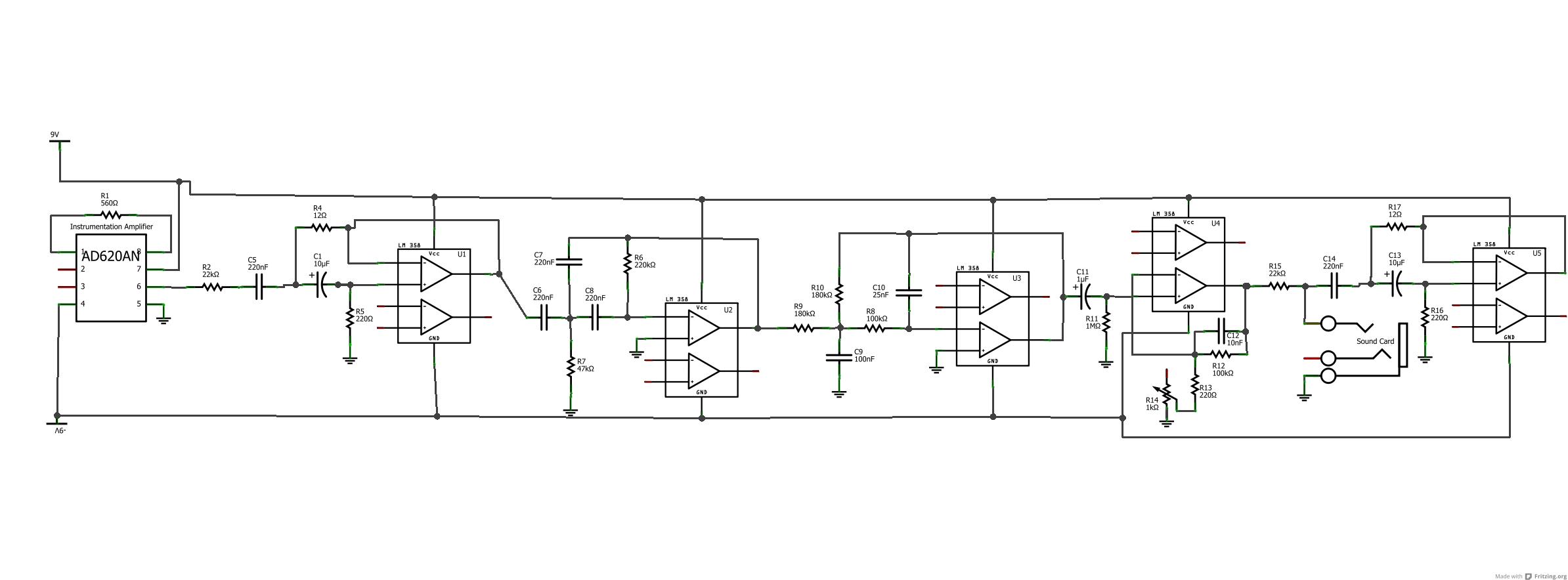
I've seen this circuit before, and it is a very poor piece of design. It uses 5 chips where 2 will do, is basically just some filter stages and a gain stage, and has no power decoupling. The hard part, a differential amp with the mandatory common mode rejection, isn't even shown. If you search for 'eeg amplifier schematic' you will get many circuits that are better.
ak
If you go visit the actual website you will find that the "extra" op-amps are only there because the author couldn't find a single op-amp symbol in his drawing package. He actually used two quad op-amps for the active filters. And there is an AD620AN used as a front-end differential-input instrumentation amplifier for two of the three electrodes. He didn't do a very good job of explaining what that third electrode was for. I didn't run a sim on the filters, but apparently they work okay as notch and band-pass filters to reject power-line radiation from wiring in the walls and noise from moving the electrode wires around. Many of the comments on the Instructables site were related to software, but who knows how well that was written? As for the details of power supply by-passing and circuit layout... NADA! Not a good feature for the beginner trying to do a "monkey say, monkey do" project, which is typical of the Instructables reader. Even with all that, I would give the author of the Instructable a "B" for a good effort, and maybe an "A" for some nice pictures of the bread-board setup. Gotta wonder whether or not he went on to put it all together in a pretty package.
Thanks all for the replies.
I think I'm going to go the route of using a multiplexer chip to cycle through my electrode inputs. Then use an Arduino to pass the information into my laptop.
Thanks all for the safety notices too. Caution and safety are my utmost concerns, and I'll be sure to be as careful as possible.
You will need one of the instrumentation amplfier/active filter circuits for
each pair of electrodes, and the multiplexing will involve using the high-level conditioned outputs
NOT the electrode leads themselves. Those electrodes must never get anywhere near the multiplexor, Arduino, or laptop circuits.
EEG signals are particularly difficult to process because the electrical activity must make its way from the brain, through the skull, and onto the skin. It is always accompanied by all sorts of electrical noise that has nothing at all to do with brain activity. Triboelectric voltage introduced by movement of the electrode wires is always a problem, best "fixed" by taping the wires down after affixing the electrodes to your head. And there are myoelectric currents to eliminate too, caused by involuntary muscle movements.
All this makes an EKG recording seem like a walk in the park, although the same considerations apply. An EKG is produced from a central location (the heart) by a very strong emitter. You almost don't even need to attach electrodes to measure heart activity, but that is where I would start. Get the EKG working and then go for the EEG instrumentation.
Actually, I have a head-start (chest-start?) on all this, having a heart pacemaker/defibrillator implanted last year that has all sorts of recording stuff inside and a remote wireless readout system by my bed. My cardiologist still insists on hooking me up for a twelve-lead EKG just about every time I visit. I think they are all amazed that I am still alive, but then their equipment
is galvanically isolated. Make sure your homemade version is too.
Remember, we are here to help. Make one of the signal conditioning boards first, power it up with a pair of 9V batteries, connect it to the souind-card input of a laptop running on internal batteries only, write some software, then let us know how the project is going. Ask some more questions if you run into problems.
Hop